background image

1-15

Chapter 1.  INTRODUCTION

„

„

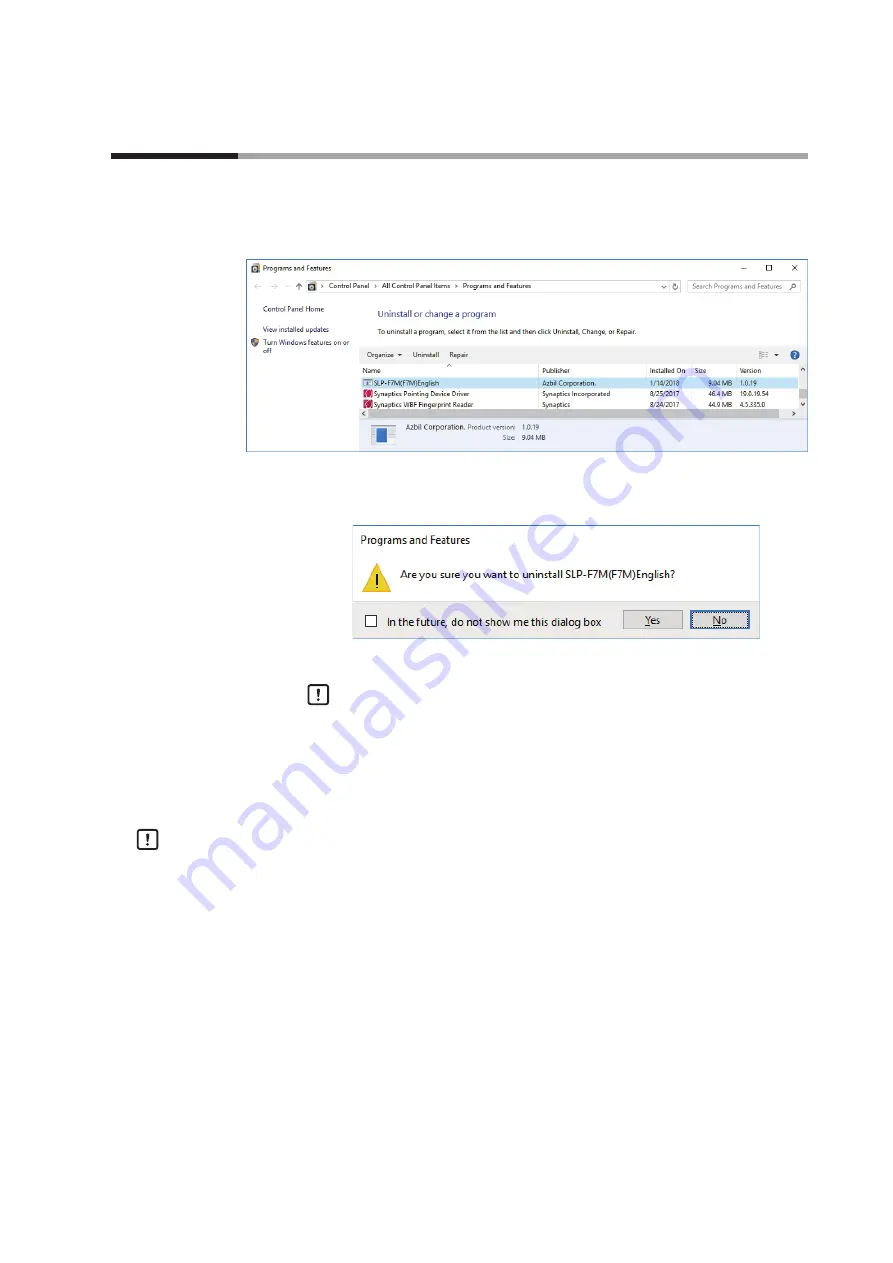
Uninstalling the Loader

(1)  Right-click the 

[Start]

 button and select 

[Programs and Features]

.

>> The following screen is displayed.

(2)  Double-click “

SLP-F7M (F7M) English

” under 

[Name]

.

>> The following screen is displayed.

(3)  Click the 

[Yes]

 button. The program and related files will be deleted.

 Handling Precautions

• 

A warning message about user account control might appear, depending 
on the PC settings. Click the [Yes] button to allow the software to make 
changes to the computer.

„

„

Uninstalling the device driver

 Handling Precautions

• 

Before uninstalling the device driver, unplug the USB loader cable from the PC.

• 

After uninstalling the driver, restart the computer.

• 

To uninstall the driver, administrator rights on the computer are required. 
Installation should be done by the administrator or by a user who belongs to 
the administrator group.

1 - 4 

Uninstallation

Summary of Contents for F7M

Page 1: ...maintaining equipment that uses this product should first read and understand this manual It provides necessary information not only for initial setup but also for changing of settings troubleshootin...

Page 2: ...anual are subject to change without notice Considerable effort has been made to ensure that this manual is free from inaccuracies and omissions If you should find an error or omission please contact t...

Page 3: ...ser should pay attention to when handling the product Note Notes indicate information that might benefit the user This indicates the item or page that the user is requested to refer to 1 2 3 Numbers w...

Page 4: ...er for loader communication cable is not water resistant Water drops or dust entering inside or accumulating around the electrodes may damage the F7M or the adapter or may cause external devices to ca...

Page 5: ...and operations of Model SLP F7M and procedures for configuring Model F7M Micro Flow Rate Liquid Flow Meter Model F7M User s Manual Manual No CP SP 1421E This manual describes the hardware and all the...

Page 6: ...tarting the loader 2 1 Exiting the loader 2 2 Checking the communication port number 2 2 Chapter 3 HOW TO USE THE LOADER 3 1 3 1 Overview 3 1 Overview of functions 3 1 Components of the screen 3 1 Loa...

Page 7: ...itor tab 3 18 3 8 Operating the Device 3 20 Adjusting the zero point 3 20 Chapter 4 TROUBLESHOOTING 4 1 Types of abnormal status 4 1 Abnormal status and corrective actions 4 1 Error messages and corre...

Page 8: ...vi MEMO...

Page 9: ...nected to the device Monitoring The operational status of the device and alarms can be checked The settings for parameters that are shown with the Write button can be written to the device immediately...

Page 10: ...cable azbil brand model No 81441177 001 3 Cable for waterproof connector Cable azbil brand model No F9Y7H_1 Software Microsoft NET Framework 4 6 If this software is not installed on the PC download i...

Page 11: ...adapter for loader communication cable The device can now be turned on or off with the power switch on the adapter for loader communication cable USB port Note 1 During loader communication output fro...

Page 12: ...apter for loader communication cable is not water resistant Water drops or dust entering inside or accumulating around the electrodes may damage the device or the adapter or may cause external devices...

Page 13: ...it before use Expanded file name example setup_SLPSP7_en_V1_0_15 msi Installing the Loader The following explanation of the loader installation and screens use 64 bit Windows 10 as an example 1 Double...

Page 14: ...the software license agreement and wish to install the software check the check box for I accept the terms in the License Agreement and click the Next button The following screen is displayed Note Cli...

Page 15: ...een is displayed Handling Precautions A warning message about user account control might appear depending on the PC settings Allow the software to make changes to the computer 6 Click the Finish butto...

Page 16: ...d installation is not successful uninstall the driver and reinstall it To install the device driver administrator rights on the computer are required Installation should be done by the administrator o...

Page 17: ...depending on the PC settings Click the Yes button to allow the software to make changes to the computer 2 Click the Next button The following screen is displayed Handling Precautions The USB loader ca...

Page 18: ...is displayed Handling Precautions If a message saying that the USB loader cable driver has already been installed on your computer appears even if you uninstalled the driver in the past follow the pr...

Page 19: ...xt button The following screen is displayed 6 If you accept the software license agreement and wish to install the software select AGREE and click the Next button Installation of the device driver sta...

Page 20: ...ce driver cannot be installed When attempting to install the device driver on a PC on which a USB loader cable was used in the past the following window may appear and it may not be possible to instal...

Page 21: ...he following screen is displayed 2 Click the Finish button The installer for the device driver closes Step 2 Follow the procedure described in Uninstalling the device driver P 1 15 Step 3 Install the...

Page 22: ...the checkbox to enable NET Framework If NET Framework is not displayed the software has not been installed After confirming that NET Framework is enabled close the window Note If the software has not...

Page 23: ...g message about user account control might appear depending on the PC settings Click the Yes button to allow the software to make changes to the computer Uninstalling the device driver Handling Precau...

Page 24: ...Programs and Features The following screen is displayed 2 Double click Azbil Loader Cable Driver The following screen is displayed 3 Click the Yes button The device driver is deleted and the following...

Page 25: ...settings button to check that is set for Decimal symbol If any other symbol is set the loader will not work properly Check the Windows power option settings and make sure that the PC will not automati...

Page 26: ...uals provided with those products Exiting the loader Select File Exit or click the icon in the upper right corner of the screen The loader closes Checking the communication port number Select Control...

Page 27: ...may be judged to be outside the range limit with the result that the number cannot be input Components of the screen Menu bar Toolbar Status bar Panel view Tab Tree view Name Description Menu bar All...

Page 28: ...o the device Ctrl O Save Saves the current parameters Ctrl S Rename and save Saves the current parameters to a file with a different file name Shift Ctrl S Exit Ends the loader program Alt F4 Comm Com...

Page 29: ...evice can be connected without exiting the loader To do so change the device that is connected to the PC and activate communication with the device using steps 6 8 Procedures for device connection In...

Page 30: ...munication port number for Yamatake USB Loader Comm Port 6 Select Comm E Activate comm on the menu bar or click the button on the toolbar The following screen is displayed 7 Turn off the power switch...

Page 31: ...LOADER If communication activation failed the following screen is displayed Click the End button Check the communication settings of the loader the state of the device and the connection to the devic...

Page 32: ...ing a parameter file without connecting the loader to the device It is possible to create a parameter file for a device before connecting it to the loader and to write the saved parameters to the devi...

Page 33: ...nting the device specifications that do not affect the loader function are displayed with hyphens Serial No 0 Signal type Analog output DI DO Firmware version 0000 3 Check that the model number and th...

Page 34: ...files and writing parameters to the device Checking parameters of the connected device The method of reading and displaying all parameters of the connected device is explained below All parameters mea...

Page 35: ...W TO USE THE LOADER The following screen is displayed 4 Click the OK button The following screen is displayed 5 Click the Parameters tab and select the item to check in the tree view The following scr...

Page 36: ...fo tab However because the underlined digits in the following example represent the device specifications that do not affect the loader function even if there are discrepancies in these digits paramet...

Page 37: ...Rename and save on the menu bar or click the button on the toolbar The following screen is displayed 2 Enter any name in the File name field and click the Save button Checking saved parameters This se...

Page 38: ...ter 3 HOW TO USE THE LOADER 2 Select the parameter file to open extension f7m and click the Open button The following screen is displayed 3 Select a tab and an item in the tree view to check parameter...

Page 39: ...parameters cannot be changed Parameters Unit Description Factory default Model No Device model No 17 chars ID code 1 alphabetical char In some cases the ID code is not printed Example F7M9030AQ1001000...

Page 40: ...00 10 00 0 00 Delay lower limit s 0 0 60 0 0 0 Analog output settings Span correction factor 0 000 2 000 1 000 Zero point correction V 1 000 to 1 000 0 000 Output at error Present value Last good val...

Page 41: ...ick the Monitor tab and select the item to display in the tree view Monitoring information has not yet been read from the device The following are the screens displayed when Monitor Process value is s...

Page 42: ...cted device P 3 8 If you have already executed steps 1 to 4 this process is unnecessary 3 Click the Monitor tab and select the desired item in the tree view At this point monitoring information has no...

Page 43: ...en is displayed in green and the word Communicating blinks Under these conditions monitoring parameters can be written to the device immediately by pressing the Write button 5 Change the value or opti...

Page 44: ...ustment for liquid type 1 The value can be changed 1 3 5 00 to 5 00 0 00 Flow rate CCF 2 Indicates the flow rate correction factor for liquid type 2 The value can be changed 1 3 0 to 100 000 1 000 Zer...

Page 45: ...status code 4 For maintenance Abnormal status code 5 For maintenance Abnormal status code 6 For maintenance Abnormal status code 7 For maintenance 1 Available on devices with ID code b or later 2 The...

Page 46: ...t If this function is used to automatically set the CCF flow rate accuracy is not guaranteed For higher accuracy use the set value as a guideline for setting the CCF manually Handling Precautions When...

Page 47: ...pe is full of fluid and that the fluid is not moving and then click the OK button The following window is displayed When zero point adjustment is complete the following screen is displayed 5 Pressing...

Page 48: ...MEMO...

Page 49: ...ital output remains off when DO function is set to Error indication output Whether a warning has occurred can be checked with the LED indicator or by the loader If a warning occurs flow rate measureme...

Page 50: ...repair 6 Al Flow path or circuit temperature out of range The sensor unit has failed Check that the fluid temperature and the ambient temperature meet the specified operating conditions If the alarm...

Page 51: ...is corrupt 13 Er Software execution error The heater or temperature sensor has failed The electric circuit has failed If the error persists after turning the power off and back on request repair 14 E...

Page 52: ...on as for The read data contains errors The read data contains errors The file could not be opened due to errors in the file The file is probably corrupt Specify the parameters again and save them to...

Page 53: ...device information must be the same as the model number of the connected device Model number specified by the loader F7M _ _ _ _ _ _ _ _ Model number of the connected device F7M _ _ _ _ _ _ _ _ Parame...

Page 54: ...eck that the pipe is full of fluid and that the fluid is not moving and try again Zero point adjustment failed Zero point cannot be adjusted if an error or alarm occurred or if zero point adjustment h...

Page 55: ...In the Windows settings select Control Panel Region and press the Additional settings button Check that is set as the decimal point symbol Other Some or all functions of the loader screen display ope...

Page 56: ...MEMO...

Page 57: ...nged a screenshot Added Handling Precautions 3 7 3 9 Changed a screenshot 3 13 3 14 Changed the table in Device info tab Changed the table in Parameter tab 3 15 Moved from p 3 14 3 15 Changed a screen...

Page 58: ...11 Specifications are subject to change without notice 1 12 2 Kawana Fujisawa Kanagawa 251 8522 Japan https www azbil com 1st edition Apr 2018 V 2nd edition Apr 2019 V...

Reviews: