


3-2
Chapter 3. HOW TO USE THE LOADER
Loader functions
The table below shows the functions of the loader. They can be executed from
the menu bar.
The functions with icons can also be executed from the toolbar.
3 - 4 List of Parameters (P. 3-13)(for device information and a list of
parameters)
•
File (F):
The submenu includes file operations and exit from the
loader.
•
Comm. (E):
The submenu includes the function to execute before
starting communications with the device.
•
Parameters (P):
The submenu includes functions for reading all
parameters from the device and writing all parameters
to the device.
•
Monitor (M):
The submenu includes functions for starting and
stopping monitoring.
•
Device operation (O): Certain device functions can be executed from the
submenu.
•
Help (H):
Loader information, etc., can be displayed from the
submenu.
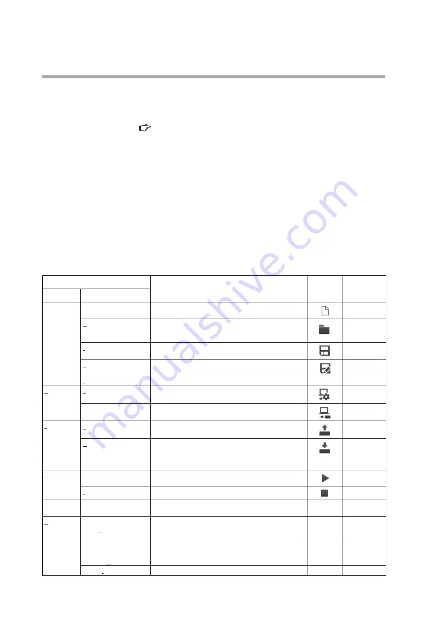
Menu bar
Overview of functions
Toolbar
Shortcut keys
Menu
Submenu
File
New
Creates a file of parameters to be written to a device, while
the loader is not connected to the device.
Ctrl + N
Open
Reads parameters that were saved to a file and displays them
on the loader screen. The parameters can be changed and
written to the device.
Ctrl + O
Save
Saves the current parameters.
Ctrl + S
Rename and save...
Saves the current parameters to a file with a different file
name.
Shift + Ctrl + S
Exit
Ends the loader program.
–
Alt + F4
Comm.
Comm. settings
Communication settings of the loader can be changed.
Ctrl + G
Activate comm.
Execute this function before starting communication.
Ctrl + A
Parameter
Read all parameters
from device
Reads device information and parameters from the device.
F1
Write parameters to
device
Writes only parameters to the device.
Device information is not written.
Settings cannot be written if the model No. of the connected
the device differs from the number in the loader.
F2
Monitor
Start monitoring
Reads the process value and device status from the device
and updates the monitoring display.
F4
End monitoring
Ends updating of values on the monitor screen.
F5
Device
operation
Zero point adjustment
Automatically adjusts the zero point of the instantaneous flow
rate.
–
F6
Help
User's Manual for SLP-F7M
Smart Loader Package for
F7M (PDF)
The user's manual for the loader can be viewed.*
–
–
F7M Micro Flow Rate
Liquid Flow Meter User’s
Manual (PDF)
The user's manual for the device can be viewed.*
–
–
Version information
The version information for the loader, etc., is displayed.
–
–
* Adobe Acrobat Reader XI or later version is required to view the document.


