IFD400 Series Pilot Guide
1-10 System Overview
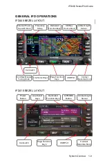
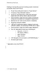
Starting in the top left corner and working counter-clockwise
around the bezel, the IFD has:
Power/Volume/Squelch knob
†
or Power Button
*
Frequency Swap dedicated button
†
Three (3) Line Select Keys (LSKs) that are page
dependent with soft key labels adjacent to each
Dual concentric rotary knob as a means of manually
tuning communication and navigation frequencies
†
Mechanical cam latch access hole for installation
Page keys along the bottom
USB port for database updates, datalog downloads,
software updates, and powering USB devices in-flight
Dual concentric rotary knob that is page dependent
Four (4) dedicated function keys consisting of:
o
Direct-
To (“─D─>”)
o
Procedure (“PROC”)
o
Enter (“ENTR”)
o
Clear (“CLR”)
CDI Navigation Source knob
†
or GPS/OBS Button
*
Ambient Light Sensor
*
Applicable only to the IFD410
Summary of Contents for IFD410 FMS/GPS
Page 1: ......
Page 8: ......
Page 56: ......
Page 100: ...IFD400 Series Pilot Guide 2 44 FMS Subsystem Info Tab Nearby Navaids ...
Page 160: ......
Page 250: ...IFD400 Series Pilot Guide 4 90 Aux Subsystem ADS B Unavailable Products Page ...
Page 252: ......
Page 378: ......

