background image

 Powering Up and Configuring the System

43

Powering Up and Configuring the System

After installing software and making S6L network connections, follow the instructions in this section to learn how to power the sys-
tem up (and down), and to configure your S6L system. 

Powering the System Up and Down

After connecting your system components for the first time, power up your system by following the steps in this section. Make sure 
you have installed the S6L System Restore software and the E6L System Restore software on the respective devices. 

For day to day operation of the system, or after performing a System Update, you can follow the instructions in 

Day to Day Pow-

ering Up and Down

First Time Power Up

Power up the system in the following sequence:

1

Power on the control surface video monitor (referred to in this and other S6L guides as the external screen).

2

Power on the E6L engine by pressing the power switch on the back to the on (1) position. On the front panel of the E6L engine, 
the LEDs light as follows:

• Status LED lights green.
• The System LED begins to flash amber while the E6L is waiting to connect to the S6L control surface, then turns green when 

connection is complete.

3

Power on the S6L control surface by pressing the power switch on the back panel 
to the on (1) position. 

The LEDs on each of the S6L’s PSUs light green, and Avid logos appear on the 
Master Touch Screen (MTS), the Channel Touch Modules (CTMs), and/or the ex-
ternal screen while the system initializes. 
If you are powering up the system for the first time after performing a System Re-
store, or the S6L control surface is connected to a different E6L engine than it was 
previously connected to, the 

Please Select Engine

 screen appears on the MTS 

(or external screen with S6L-16C) when initialization is complete. 

.

If you have not installed the System Restore software on your S6L control surface, on initial power-up S6L prompts you to install 
software or shut down your system. For System Restore instructions, see 

VENUE System Restore

Make sure no VGA monitor, mouse, keyboard, or internet is connected to the E6L engine before powering up your S6L system.

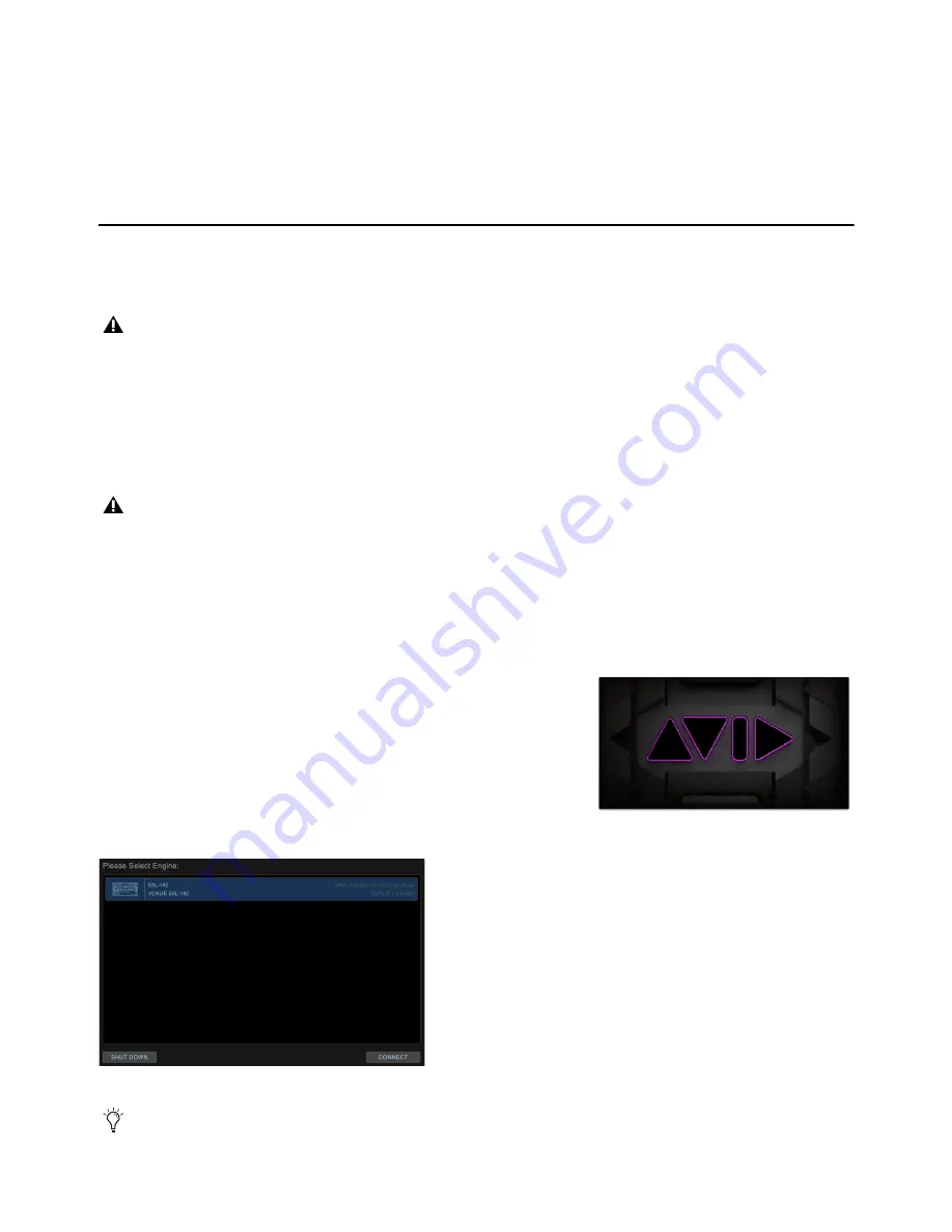
Please Select Engine Screen on the MTS

If an alert is shown telling you to Activate Windows, ignore it for now (you will activate Windows later, after powering up. 

Avid logo on-screen

Summary of Contents for VENUE Local 16

Page 1: ...Avid VENUE S6L Installation Guide...

Page 2: ...es Bonjour the Bonjour logo and the Bonjour symbol are trademarks of Apple Computer Inc Thunderbolt and the Thunderbolt logo are trademarks of Intel Corporation in the U S and or other countries This...

Page 3: ...not use this equipment near water 6 Clean only with dry cloth 7 Do not block any ventilation openings Install in accordance with the manufacturer s instructions 8 Do not install near any heat sources...

Page 4: ...CAUTION This unit has more than one power supply cord Disconnect two power supply cords before servicing to avoid electrical shock ATTENTION Cet appareil comporte plus d un cordon d alimentation Afin...

Page 5: ...de and other VENUE S6L guides and documentation and to become familiar with some of the Resources available at www avid com Then do the following as appropriate for your installation If you are instal...

Page 6: ...at appear on screen are in a different font The following symbols are used to highlight important information Hardware Switches on Control Surfaces The names of switches on the control surfaces are in...

Page 7: ...documents for system requirements search the online Knowledge Base or join the worldwide Avid user community on the User Conference https www avid com products venue s6l system learn and support Trai...

Page 8: ...Part I First Time Setup...

Page 9: ...Sound Production Toolkit VENUE S6L Control Surface Software Plug Ins Pack The S6L Control Surface Software and Plug Ins pack includes the following S6L Control Surface Restore USB Drive Use this USB d...

Page 10: ...pack includes the following E6L Engine Restore Drive Use this USB drive to store E6L Engine System Restore software and to initially install system soft ware on your E6L After initial installation ke...

Page 11: ...xternal digital devices DB25 25 pin cable s for connecting to GPI devices iOS devices for VENUE On Stage and VENUE Function Pad apps Expansion Options S6L systems can be expanded to add analog or digi...

Page 12: ...n any S6L system component Do not operate in direct sunlight or at extreme ambient temperatures Water and Moisture S6L system devices should be operated away from sources of direct moisture and should...

Page 13: ...ollows SMF Requires single mode 9 125 OS1 or OS2 cables with duplex LC connectors and two qualified single mode SFP transceivers per connection supporting distances of up to 10 kilometers MMF Requires...

Page 14: ...ep cables and other included items organized making sure to keep them with their associated component after unpacking Installing the E6L Bezel After mounting the E6L in a rack or other enclosure you c...

Page 15: ...S6L system devices and must be released when disconnecting To release an included IEC cable from an AC power inlet on an S6L system device Simultaneously slide the two tabs on either side of the conn...

Page 16: ...to open a web browser An Internet connection is required to transfer licenses to and from your iLok com account 2 Visit www account avid com and create an Avid Master Account If you already have an a...

Page 17: ...Part II Software Installation...

Page 18: ...figuring a system for the first time For instructions proceed to VENUE System Restore If you are upgrading an already configured system The most recent VENUE software can be installed as either a comp...

Page 19: ...e instructions in Backing Up System Settings before proceeding System Restore Software Installation Overview After Unpacking and Assembling Basic System Components and Activating S6L System Components...

Page 20: ...ma chines are supported then proceed to Creating System Restore USB Drives Creating System Restore USB Drives Windows XP or Higher and the Included System Restore USB Drives Required After downloadin...

Page 21: ...eted remove the USB drive from the computer and then label the drive E6L Engine Restore Creating an S6L Control Surface System Restore USB Drive To create an S6L Control Surface System Restore USB Dri...

Page 22: ...n the E6L E6L provides two USB ports on the front panel and two on the back panel An Ethernet cable from your Internet source router or modem to the Ethernet RJ 45 port on the back of the E6L A VGA co...

Page 23: ...be physically connected to an Internet source Ethernet cable required Wi Fi not supported Activating Windows on E6L To activate Windows and RTX64 on your E6L engine 1 When the E6L restarts after inst...

Page 24: ...X64 Ultimate Configured appears in the window 5 Close the RTX64 Activation and Configuration window 6 Double click the Shut Down the System shortcut on screen 7 Wait until the front panel Status LED i...

Page 25: ...rts on the back of the S6L control surface to the USB port on the monitor 2 Insert the S6L Control Surface System Restore USB Drive into an available USB port on S6L 3 Power on your S6L control surfac...

Page 26: ...Restore 6 Do either of the following as appropriate for your situation If you see any messages about needing to update Pace software see Updating the BIOS Otherwise proceed to Configuring S6L Master...

Page 27: ...o Select Solo Select Solo Select Solo Select Solo Select Solo B A S Menu Safe Mute Y X Y X Y X Y X Y X Y X Y X Y X B A S Menu Safe Mute B A S Menu Safe Mute B A S Menu Safe Mute B A S Menu Safe Mute B...

Page 28: ...re Not all versions of VENUE software can be installed as a Software Update When one is available it is provided for download in your Avid account To determine the currently installed version of VENUE...

Page 29: ...example VENUE 6_X_xx_S6L_Console_Restore zip VENUE 6_X_xx_E6L_Engine_Restore zip VENUE_Update_6_X_xx zip 4 After download is complete extract each ZIP file and in their resulting folders locate the re...

Page 30: ...Console in the left column select the items you want to transfer from your system to your portable storage de vice The items that appear in the left column depend on the type of data selected in the c...

Page 31: ...structure should look similar to the inage shown at right 8 Make sure you have connected a DVI monitor keyboard and mouse directly to the S6L control surface and that you have disconnected all speake...

Page 32: ...e the E6L Engine do the following Insert the USB drive containing the VENUE_Update folder into any available USB port on the back of the E6L Engine On the computer keyboard press Ctrl Shift U When the...

Page 33: ...Part III Network Connections...

Page 34: ...er and fiber connected to the same network port simultaneously The instructions and diagrams in this guide show copper Ethernet connections only between RJ 45 ports on components For in formation on c...

Page 35: ...rk port A to E6L port Master port B E6L Master port A to Stage IO unit port B and Stage IO unit s port A to S6L port B In Figure 1 the redundant ring is established by the connection from the Stage I...

Page 36: ...he CONNECTED column followed by Stage 32s if any followed by Stage 16s if any For more information see Virtual Soundcheck Important Note 6 Local 16 I O Local 16 I O can be connected to provide I O at...

Page 37: ...ng the System Up and Down Supported Audio Network Configurations Configurations click for instructions Stage Inputs max Stage Outputs max AVB 192 Cards required Example 1 Basic Single System 64 32 1 E...

Page 38: ...48V SIG 48V SIG 48V SIG 48V INPUT SRI 192 1 2 3 4 5 6 7 8 SIG 48V SIG 48V SIG 48V SIG 48V SIG 48V SIG 48V SIG 48V SIG 48V INPUT SRI 192 1 2 3 4 5 6 7 8 SIG 48V SIG 48V SIG 48V SIG 48V SIG 48V SIG 48V...

Page 39: ...B AVB 192 ACT SIG ACT SIG ACT SIG ACT SIG A B A B A B AVB 192 ACT SIG ACT SIG ACT SIG ACT SIG A B A B C D E F G H J K L M 1 2 3 4 5 6 7 8 SIG 48V SIG 48V SIG 48V SIG 48V SIG 48V SIG 48V SIG 48V SIG 48...

Page 40: ...D E F G H J K L M 1 2 3 4 5 6 7 8 SIG 48V SIG 48V SIG 48V SIG 48V SIG 48V SIG 48V SIG 48V SIG 48V INPUT SRI 192 1 2 3 4 5 6 7 8 SIG 48V SIG 48V SIG 48V SIG 48V SIG 48V SIG 48V SIG 48V SIG 48V INPUT SR...

Page 41: ...audio network connections required 3 IN OUT NETWORK MASTER 1 WORD CLOCK UTIL EXPANSION 2 3 6 7 8 1 2 3 4 5 OK OK A B AVB 192 ACT SIG ACT SIG ACT SIG ACT SIG A B AVB 192 ACT SIG ACT SIG ACT SIG ACT SI...

Page 42: ...lowest setting 10 and shows negative values up until the stage gain reaches 20 When no Stage 64s are present up to two Stage 32s and up to four Stage 16s can be connected as shown in the example diag...

Page 43: ...to the second Stage I O by connecting Network port A on the first Stage I O to Network port B on the second Stage I O Repeat for any additional Stage I O units connect A to B 5 Connect an Ethernet cab...

Page 44: ...ards connect the S6L control surface to the top most AVB Network card on its corresponding E6L engine 1 2 On each pair of E6L engine and S6L control surface connected in step 1 1 connect an Ethernet c...

Page 45: ...8V SIG 48V SIG 48V SIG 48V INPUT SRI 192 1 2 3 4 5 6 7 8 SIG 48V SIG 48V SIG 48V SIG 48V SIG 48V SIG 48V SIG 48V SIG 48V INPUT SRI 192 1 2 3 4 5 6 7 8 SIG 48V SIG 48V SIG 48V SIG 48V SIG 48V SIG 48V S...

Page 46: ...Part IV Completing the Installation...

Page 47: ...begins to flash amber while the E6L is waiting to connect to the S6L control surface then turns green when connection is complete 3 Power on the S6L control surface by pressing the power switch on the...

Page 48: ...front panel of the Stage I O unit The Status LED lights green The AVID logo appears while the device initializes Stage 64 only When initialization is complete the Controller Menu HOME page is shown 6...

Page 49: ...page The Devices page lets you connect and trouble shoot system components view their status and edit hardware settings If you are configuring a system for the first time the Connected Devices column...

Page 50: ...and components were already paired prior to performing a Software Update you should not need to pair them again if this is the case proceed to Setting the System Clock If you ever need to re assign co...

Page 51: ...ws is part of the VENUE software installation on your S6L control surface and must be activated separately from VENUE software and separately from the Windows activation on the E6L engine To activate...

Page 52: ...ows Windows Activation is complete when Product activated successfully Press any key to continue appears in the activation window on screen 4 Disconnect the Ethernet cable from the ECx port 5 Proceed...

Page 53: ...face The Config switch lights and Config is indicated in the Mode box in the on screen Status Bar Or On screen double tap the Mode box in the Status Bar located in lower right hand corner of the scree...

Page 54: ...e 16 configure Stage slots in the CONNECTED column by clicking to select the slot and then choosing the appropriate device from the selector 4 In the AVAILABLE column select the first Stage I O device...

Page 55: ...ons System tab Select Shut Down then select Shut Down again to confirm 11 Power down all connected components by pressing their back panel power switches to the off 0 positions and leave all com ponen...

Page 56: ...ge I O unit flash 5 Select Identify again to turn it off If any connected Stage I O units do not appear in the Available Devices section check network and power connections The Identify button left an...

Page 57: ...nnecting them to the Ring 2 S6L network ring To assign Local 16 1 Make sure the system is in Config Mode see Enabling Config Mode 2 Navigate the external screen to Options Devices 3 In the NETWORK CAR...

Page 58: ...zone 5 Select each available field and enter the appropriate data to set the time and date 6 Select Apply The new System Clock settings are applied How to Proceed If prompted to activate Windows be su...

Page 59: ...face to the router or client computer Network Connection Guidelines for ECx Unsupported ECx connections can destabilize VENUE when connected to a large net work The ECx port on the S6L control surface...

Page 60: ...ily identify it as containing the licenses for your S6L system plug ins such as S6L Plug Ins Copying the Plug Ins Installer to a USB Drive To copy the plug ins installer to a USB drive 1 Make sure the...

Page 61: ...e available in your Avid account ECx Ethernet Control Software ECx is installed separately on both your S6L system and a client computer or other mobile de vice for remote control of your VENUE system...

Page 62: ...lkit license to your iLok 1 Locate the Pro Tools iLok and insert it into an available USB port on your computer 2 Launch the iLok License Manager 3 In the License Manager select the Live Sound Product...

Page 63: ...Part V Reference...

Page 64: ...h to the On position for the PSU that is plugged into an AC power source If both PSUs are connected for redundancy power on both PSUs The power switch es lights green On the front panel of the Stage 6...

Page 65: ...ry shut down your system and power off all components 2 Make sure a VGA monitor and USB keyboard and mouse are still connected to your E6L engine 3 Power on your E6L engine and repeatedly press F5 on...

Page 66: ...uded with VENUE 6 x x software and available for download at https rufus ie en_IE html After collecting all the required components proceed to Creating the BIOS 50 Update Key Creating the BIOS 50 Upda...

Page 67: ...d F5 keys to access the Win dows boot menu While on this screen wait at least 2 minutes and 30 seconds 8 After waiting at least 2 minutes and 30 seconds press the Enter key on your computer keyboard t...

Page 68: ...e the dust plug from the SFP module s port and set it aside for later use 5 Remove the dust cap from the fiber optic cable connector align the connector with the port so that the tab on the top of the...

Page 69: ...igure system Stage I O You can reconfigure Stage I O on the Op tions Devices tab any time after the initial system set up and configuration You can reassign connected Stage I O racks remove Stage I O...

Page 70: ...e Forget Engine On subsequent restarts the S6L will not attempt to pair with any E6Ls on the network Any pairings to an E6L must be made man ually see Pairing the E6L and S6L Managing E6L Stage I O Co...

Page 71: ...and assign Stage I O racks 1 Make sure your system is in Config mode 2 On the external screen go to the Options Devices page and locate the Connected Devices column By default three Stage 64 slots ar...

Page 72: ...ssign Stage 64s if any to the lowest numbered slots 1 3 whenever possible followed by any Stage 32s followed by any Stage 16s 4 In the Available Devices column select the desired Stage I O device so i...

Page 73: ...cal Support USA Visit the Online Support Center at www avid com support Product Information For company and product information visit us on the web at www avid com Avid 75 Network Drive Burlington MA...

Reviews: