


Chapter
C
: Fuel, Air Induction, and Exhaust Systems Diagnosis and Repair
63
can be only on or off. However, by changing the ratio of
on-time to total cycle time, the powertrain control mod-
ule (PCM) can control how much work the solenoid per-
forms. Work can be performed only when there is cur-
rent available. On a solenoid that is switched to ground
by the PCM, current is available when the signal voltage
is low. More or less work can be performed by varying
the amount of time the solenoid is switched on during
each cycle. This practice of varying the on-time ratio is
called pulse width modulation (PWM). The pulse width
is the amount of time a solenoid is energized, or on, dur-
ing one cycle and is usually measured in milliseconds
(ms).
The duty cycle of a solenoid is the percentage of the
cycle during which the solenoid is energized, or per-
forming work. Duty cycle is the ratio of the pulse width
to a complete cycle expressed as a percentage. A sole-
noid operating at a zero percent duty cycle is never on
and is not performing any work. A solenoid operating at
a 100 percent duty cycle is always on and working
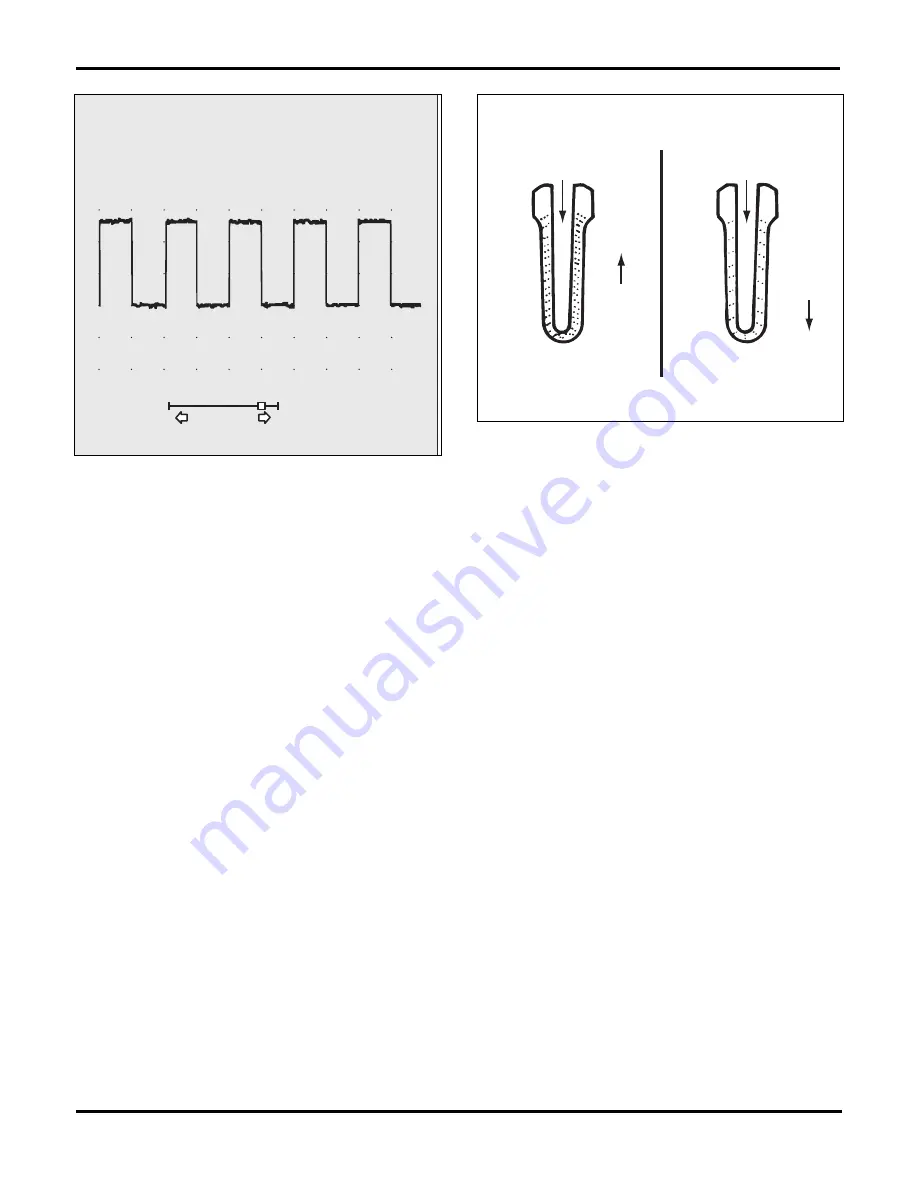
working constantly. A 50 percent duty cycle means the
solenoid is energized for 50 percent of the total cycle
and off the other 50 percent of the time, figure 3-17. A
solenoid operating at a 75 percent duty cycle is on 75
percent of the time and off during 25 percent of each
cycle.
An electronic fuel injector is a good example of a vari-
able pulse width actuator. A fuel injector also operates
at a variable
frequency
. The computer changes injector
pulse width, in relation to the amount of fuel needed by
the engine, based on input from system sensors. A short
pulse width delivers little fuel; a longer pulse width de-
livers more fuel. However, fuel injectors do not operate
at a fixed frequency, and their cycle varies with engine
speed. When the injector opens is determined by the
frequency of the signal, and how long it stays on is de-
termined by the pulse width of the signal.
Oxygen Sensor Service
All current fuel injection systems utilize at least one oxy-
gen sensor. Originally referred to as an "O2S" now is
known as a heated oxygen sensor or "HO2S". This book
will refer to the sensor as the HO2S or simply the oxy-
gen sensor, figure 3-18. in the amount of oxygen in the
exhaust vs. the outside air.
The most common HO2S made of zirconium dioxide or
zirconia. A zirconia HO2S generates a maximum output
voltage of approximately 1 volt and produces a signal
range of about 0.1 to 0.9 volt (100 to 900 mV).
The amount of oxygen in the exhaust, compared to the
amount of oxygen in the outside air, determines how
much voltage the HO2S generates. A zirconia oxygen
sensor must warm to at least 300° C (572° F), before it
can generate a valid signal.
When working on vehicles with an oxygen sensor, ob-
serve these precautions:
• Do not obstruct the vent holes on the sensor
• Use only a high-impedance digital voltmeter to test
sensor output
• Do not use silicone sprays near a oxygen sensor
• Use only HO2S-safe RTV
6V
BACK
SELECT
SEARCH
4
2
0
5ms/DIV
-2
-4V
HOLD
102
RECALL
5.28
50.0
5.00
Hz FREQUENCY
V
%
ms
PEAK-PEAK
DUTY CYCLE
PULSE WIDTH
Fig. 3-17.
The on (low-voltage) time and off (high-voltage) time of a
solenoid operating at a 50 percent duty cycle are equal.
OXYGEN SENSOR ELEMENT
ATMOSPHERE
21%
OXYGEN
ATMOSPHERE
21%
OXYGEN
EXHAUST
0%
OXYGEN
EXHAUST
2%
OXYGEN
MORE
CONDUCTION
LESS
CONDUCTION
GENERATED
SIGNAL
0.3 v
0.6 v
GENERATED
SIGNAL
Fig. 3-18.
The HO
2
S generates a voltage based on the difference in
the amount of oxygen in the exhaust vs. the outside air.
Summary of Contents for ASE-A8
Page 2: ......