


Chapter
B
: Ignition System Diagnosis and Repair
42
Ignition Cable Service
Excessive resistance in the secondary circuit can cause
driveability problems such as an engine misfire, higher
burn voltage, and shorter burn time. Damaged cables
are often the cause, and can be tested with an ohmme-
ter. Typical suppression-type spark plug wires should
measure about 4,000 ohms per foot.
Excessive resistance can result from:
• Loose or corroded connections at the distributor
cap terminal or spark plug
• Damage to the cable conductor from heat, vibra-
tion, or mishandling
Test cable resistance as follows:
1. Remove the distributor cap from the housing and
disconnect the wire to be tested at the spark plug,
or coil, end.
2. Disconnect the other end of the cable to be tested
from the distributor cap.
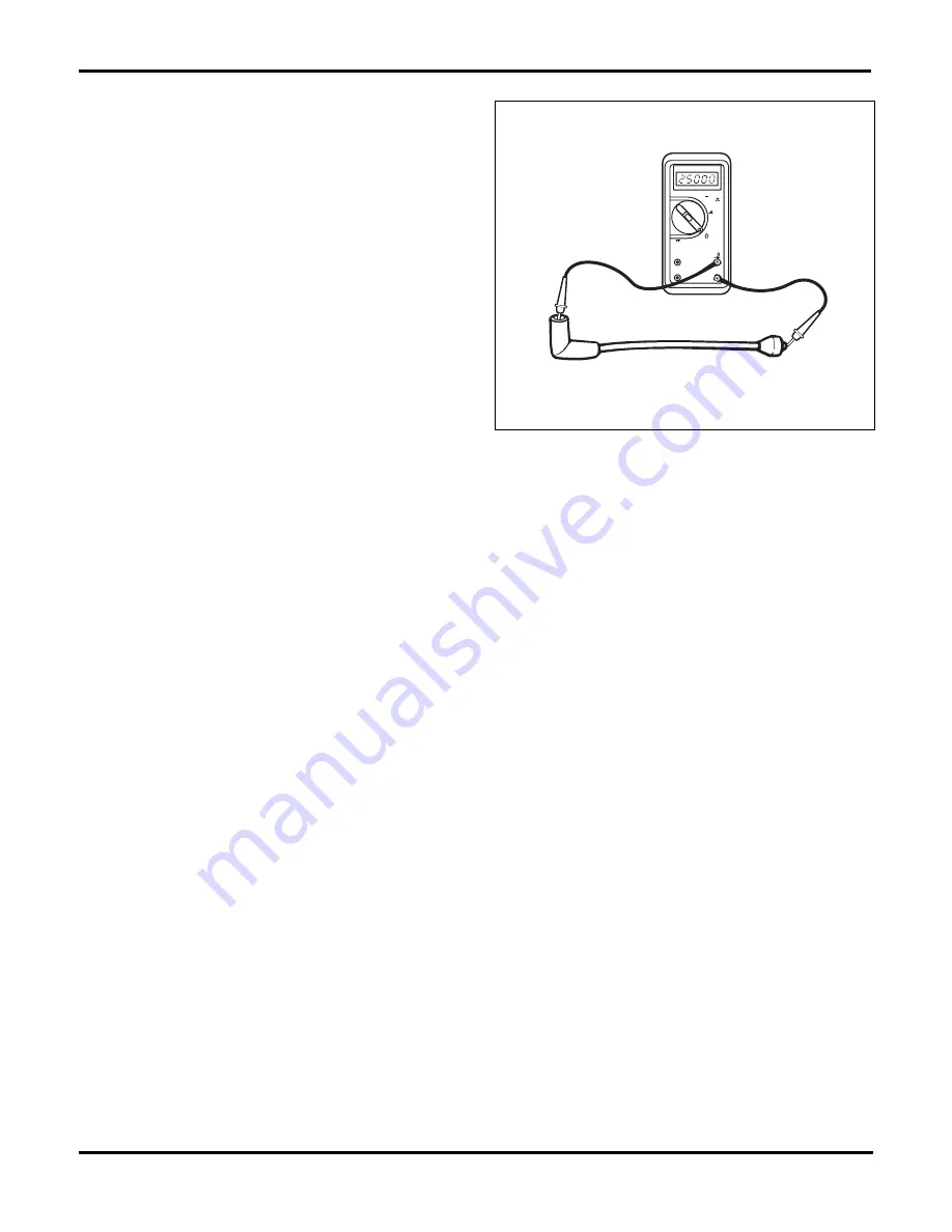
3. Set the ohmmeter on a high scale, then connect
one meter lead to each end of the spark plug cable,
figure 2-15. If meter readings are out of specifica-
tion, replace the cable.
Cable Replacement
Most ignition systems use 7-mm cables. However, oth-
ers use larger 8-mm cables. The larger cables provide
additional dielectric resistance in a system where sec-
ondary voltages can exceed 40 kV. Use the proper size
cables; they are not interchangeable.
Ignition cables generally push-fit into the distributor cap
or DIS coil. Twist and pull up on the boot to remove the
cable from the cap. Check the cap tower or DIS termi-
nal for dirt, corrosion, or damage. Clean light deposits
in the tower with a wire brush. Replace a cap or coil if
there is heavy accumulation. Fit the new cable to the
cap so the terminal seats firmly on the tower. Fit the rub-
ber boot seal over the tower, or DIS terminal, and
squeeze it to remove any trapped air.
Some distributor caps use a male ignition cable termi-
nal that looks much like a spark plug. The cable end
snaps onto the terminal instead of fitting down inside
the cap tower.
When replacing cables, disconnect only one cable at a
time from a spark plug and the distributor cap or DIS coil
terminal. For distributors, begin with the cable for cylin-
der number one and work in firing order sequence.
Route each cable in the same location as the one re-
moved and secure it into the cable brackets. To prevent
the possibility of crossfiring, do not route cables in firing
order sequence next to each other. Make sure that the
cables cannot contact the exhaust manifold or interfere
with other electrical wiring.
Ignition Coils
Primary wiring and connectors are a potential source of
high-resistance, as well as open or grounded circuits.
Problems in this area can be found with simple volt-
meter and ohmmeter tests. Check for correct supply
voltage first. If voltage is present, check for a voltage
drop using a voltmeter. When voltage drop indicates
high or low resistance, verify with an ohmmeter. Many
problems can easily be solved by cleaning connectors
or repairing wiring.
Available Voltage
Check available voltage at the coil with a voltmeter by
connecting the positive voltmeter lead to the positive
(battery) coil terminal and the negative voltmeter lead to
ground. Turn the ignition switch on and note the volt-
meter reading. On some systems, full battery voltage
should be available at the coil. On other systems, a bal-
last resistor provides a low-voltage signal to the coil.
Check the Service Manual for the correct specifications.
If voltmeter readings are not within specifications, check
the primary circuit. Repair or replace any loose or dam-
aged connections and repeat the test. If available volt-
age readings are still out of range, check the circuit for
a voltage drop.
VHz~
~
10A
RPM
+
COM
A
C F
RPM
V
%
OFF
VHz
OHMMETER
HIGH TENSION WIRE
Fig. 2-15.
Checking spark plug wire resistance with an ohmmeter.
Summary of Contents for ASE-A8
Page 2: ......