


Chapter
E
: Computerized Engine Control Diagnosis And Repair (Including OBD II)
98
vacuum pump to perform an operating range test. Ex-
pect frequency to be high with low manifold vacuum
and low at high vacuum. Be aware, the frequency of a
pressure sensor signal varies with atmospheric pres-
sure, so it changes with altitude. A unit that is out of cal-
ibration can produce a waveform that looks good but is
operating at the wrong frequency. Check the service
manual for correct specifications.
Temperature Sensor
Temperature measurement is critical for an automotive
control system because most operating parameters ad-
just to compensate for changes in operating tempera-
ture. Most control systems use a negative temperature
coefficient (NTC) thermistor as an ECT sensor. If an in-
take air temperature (IAT) sensor is used, it will be a ther-
mistor as well. An NTC thermistor is a variable resistor,
which transmits an analog voltage signal that decreas-
es as temperature increases.
The PCM applies a reference voltage, usually 5 volts,
through a pull-up resistor, to the thermistor directly on
the signal wire. As the thermistor heats up, it pulls the
reference voltage closer to ground. By monitoring the
reference signal, the PCM determines temperature
based on how much of the signal voltage is dropped
across the thermistor, figure 5-18. Some sensors use an
internal shunt circuit to increase their operating range.
Thermistors have a two wire circuit: reference and
ground.
erally use either a piezoresistive crystal or a capacitive-
ceramic device to generate an input signal to the PCM.
The resistance of a piezoresistive crystal changes when
pressure is applied to it, causing it to produce an ana-
log signal. Capacitive-ceramic units use manifold vacu-
um to vary the distance between two plates and trans-
mit a digital signal.
The PCM applies a reference voltage, usually 5 volts, to
a piezoresistive crystal. On a typical MAP sensor, one
side of the piezoresistive crystal is inside a sealed refer-
ence chamber, and the other side is in a chamber con-
nected to intake manifold vacuum. Changes in manifold
vacuum provide a variable pressure, which acts on the
crystal to vary its resistance. The resistance of the crys-
tal determines how much of the reference voltage drops
before returning to the PCM as signal voltage.
Piezoresistive sensors require a three wire circuit: refer-
ence, signal, and ground, figure 5-16. Typically, signal
voltage is low, about 0.5 volt, when manifold vacuum is
high, such as at idle. As manifold vacuum decreases,
the signal voltage increases. Signal should be about
4.75 volts, with the key on and the engine off. To check
an analog piezoresistive sensor, monitor signal voltage
on a DMM while applying vacuum with a hand pump.
Some MAP sensors work under the same principle but
produce a digital signal with variable frequency instead
of an analog voltage. Operation of this type of sensor is
best analyzed with a lab scope, figure 5-17. Use a hand
1000
1200mV
BACK
SELECT
SEARCH
800
600
400
200ms/DIV
200
0
HOLD
800
RECALL
0.00
mV MAXIMUM
V
MINIMUM
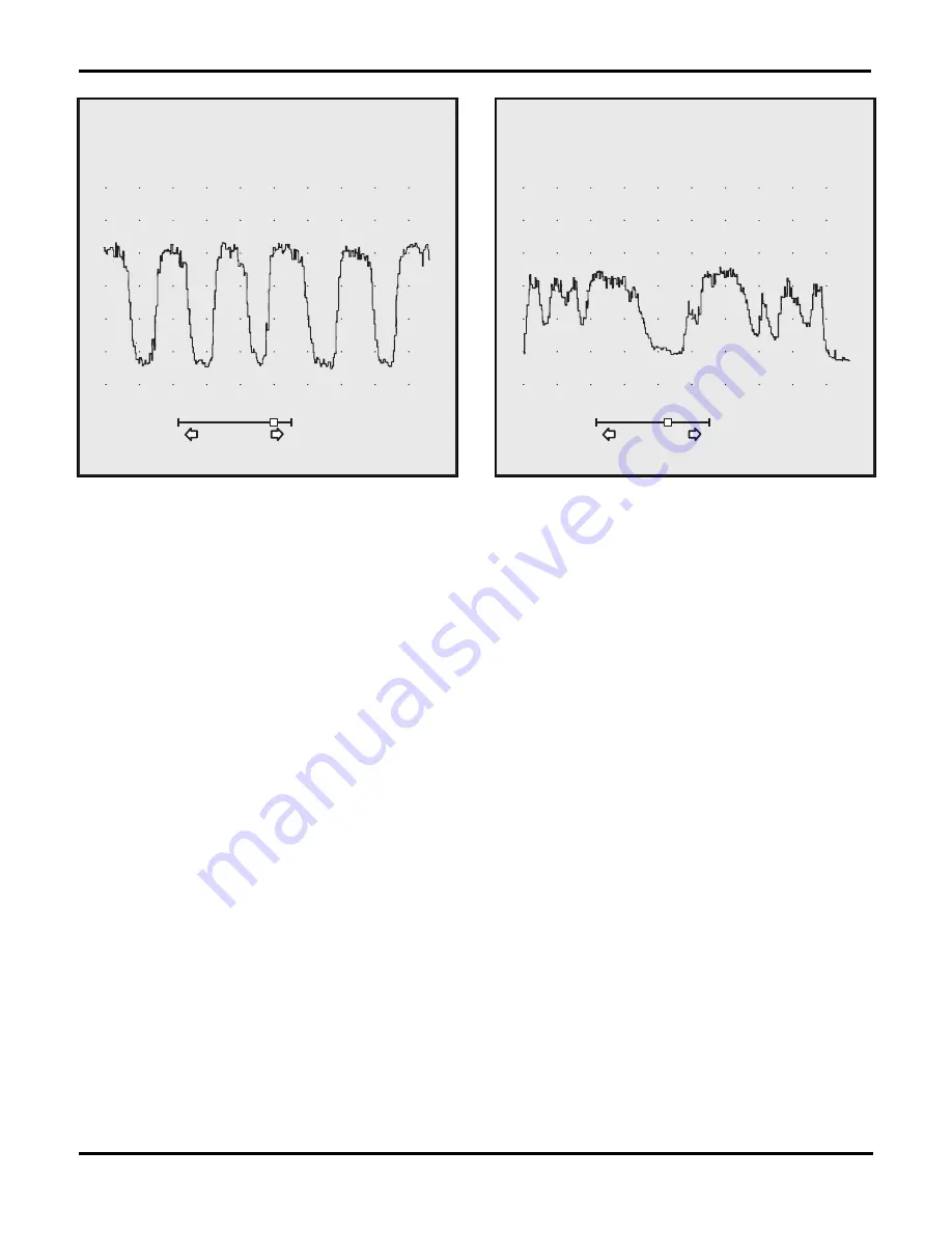
Fig. 5-11.
A good HO
2
S scope trace features rounded peaks and
even amplitude.
900
1000mV
BACK
SELECT
SEARCH
800
600
400
500ms/DIV
200
0
HOLD
760
RECALL
184
mV MAXIMUM
mV MINIMUM
Fig. 5-12.
Short or clipped peaks on an HO
2
S trace indicate
combustion or fuel mixture problems.
Summary of Contents for ASE-A8
Page 2: ......