


Chapter
B
: Ignition System Diagnosis and Repair
36
Sources of high primary resistance include:
• Loose, corroded, or damaged wiring connections
• An incorrect or defective coil
• A poor ground at the ignition module Low source
voltage can be caused by the following:
• Excessive starter motor current draw
• Low charging voltage
• A discharged battery
Primary Circuit Voltmeter Tests
First, make sure the battery has the correct performance
rating and is fully charged. Then, disable the ignition
system following the specific procedures provided by
the manufacturer. Next, check for:
• Available voltage while cranking
• Voltage-drop across the battery ground
To test voltage available from the battery while cranking,
you can monitor the data stream with a scan tool, or:
1. Connect the voltmeter positive lead to the positive
battery terminal, not to the cable connector. Con-
nect the voltmeter negative lead to a good ground.
2. Switch the ignition key on and take a voltmeter
reading while the engine is cranking.
A reading of ten volts or more indicates the battery is in
good condition. Low readings can be caused by a volt-
age drop across the battery ground cable, excessive
starter motor current draw, or incorrect charging system
output.
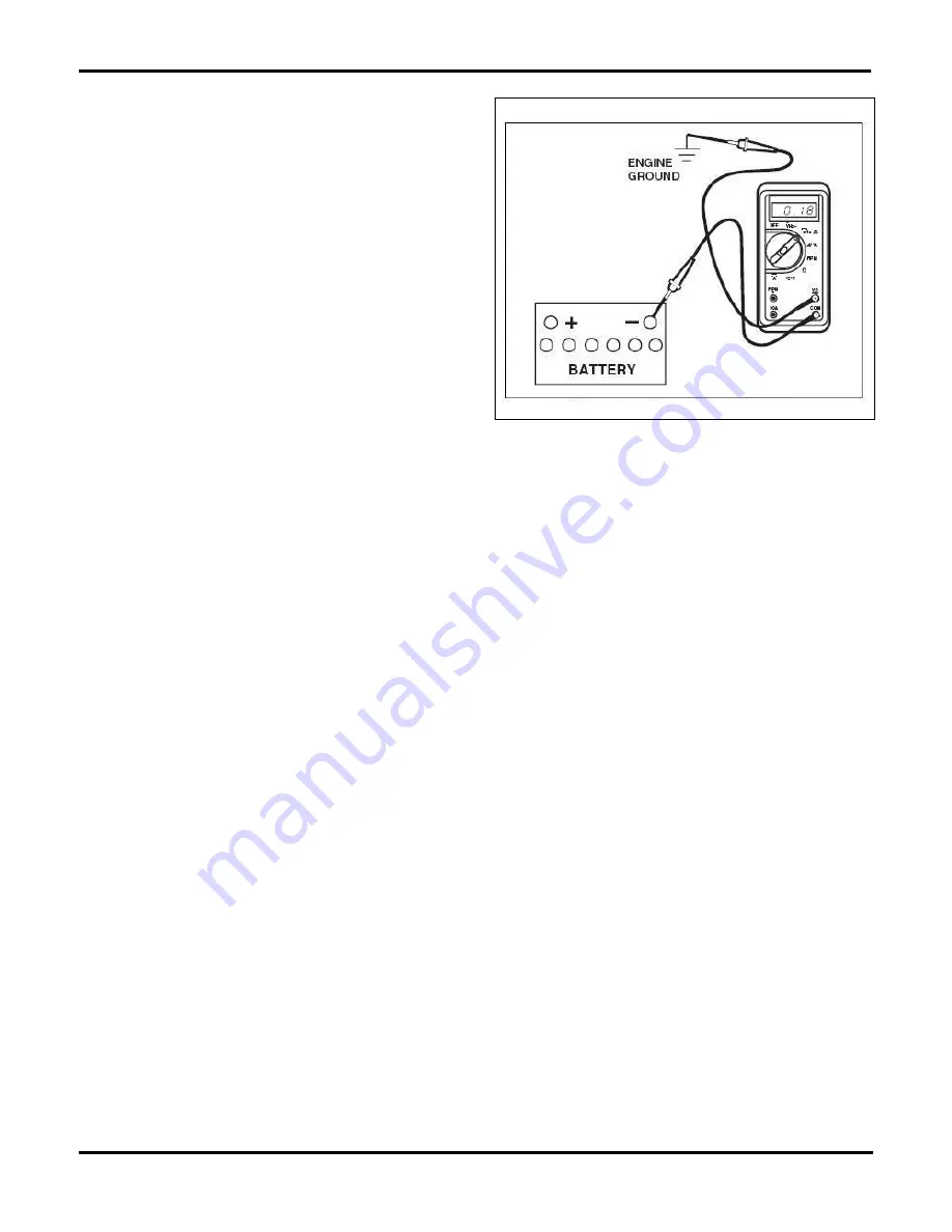
To test voltage drop across the battery ground cable:
1. Connect the voltmeter positive lead to ground and
the negative lead to the negative battery terminal,
not to the cable connector, figure 2-2.
2. Crank the engine with the starter and take a volt-
meter reading.
If the reading is 0.2 volt or less, the battery ground con-
nection and cable are in good condition. When readings
exceed 0.2 volt, clean and tighten the battery cable con-
nections and terminals. Repeat the test; replace the
ground cable if readings remain high.
Additional ignition test procedures, and the equipment
used vary by system. Accurate specifications and in-
structions from the manufacturer are required. The fol-
lowing paragraphs discuss general procedures for test-
ing a variety of electronic components.
Electronic Component Testing
Primary ignition failures often originate from problems
in the:
• Primary wiring and connectors
• Distributor signal generator
• Ignition control module
• Ignition coil
• Oxygen sensor heater
When voltage drop indicates high or low resistance, dis-
connect power and verify your findings with an ohm-
meter. Most manufacturers provide resistance specifi-
cations for components and circuits. Many problems
can easily be solved by cleaning connectors, related
grounds, or repairing damaged wiring.
In general, an electronic ignition system functions as fol-
lows: The distributor signal generator sends a signal to
the PCM. The PCM modifies the timing and sends the
signal to the ignition control module to toggle the pri-
mary coil circuit and fire the spark plugs. Some signals
are generated by a pickup coil or Halleffect switch
mounted in the distributor housing. Direct, or distribu-
torless ignition systems use a crankshaft position (CKP)
sensor to generate an input signal to the ICM, figure
2-3. The ICM provides the output signal to toggle the
primary circuit and initiate firing. The system may use an
additional camshaft position (CMP) sensor to determine
cylinder phasing and achieve more accurate control of
plug firing and timing advance, figure 2-4.
Methods to determine whether an ICM is good or de-
fective varies between systems. Procedures outlined by
the vehicle manufacturer must be followed. In general,
eliminate all other possibilities before condemning the
module. Verify power is available to the module, and
check for voltage drop across connections on the
power and ground circuits. Since modules provide the
primary circuit ground connection, many problems can
be solved by checking and cleaning the ground.
Fig. 2-2.
Voltage drop at the battery ground cable should be less
than 0.2 volt.
Summary of Contents for ASE-A8
Page 2: ......