20
M3060 User Instructions
3
Installation
3.
Route the cable to the desired power source connection point. If possible, run
the power cable through existing holes and channels so that it will be out of the
way and cannot be damaged by any moving parts. Be sure to keep the cable
from running near a distributor cap, the spark plugs or wires, or the alternator
on the motor. Keep the cable around the periphery of the engine compartment
whenever possible.
4.
Pull through all the slack in the cable and cable tie the power cable in
appropriate places to hold it in place.
5.
Disconnect the power connector from the back of the indicator.
6.
Install the fuse kit between the power cable and the connection point by
following these steps:
6a.
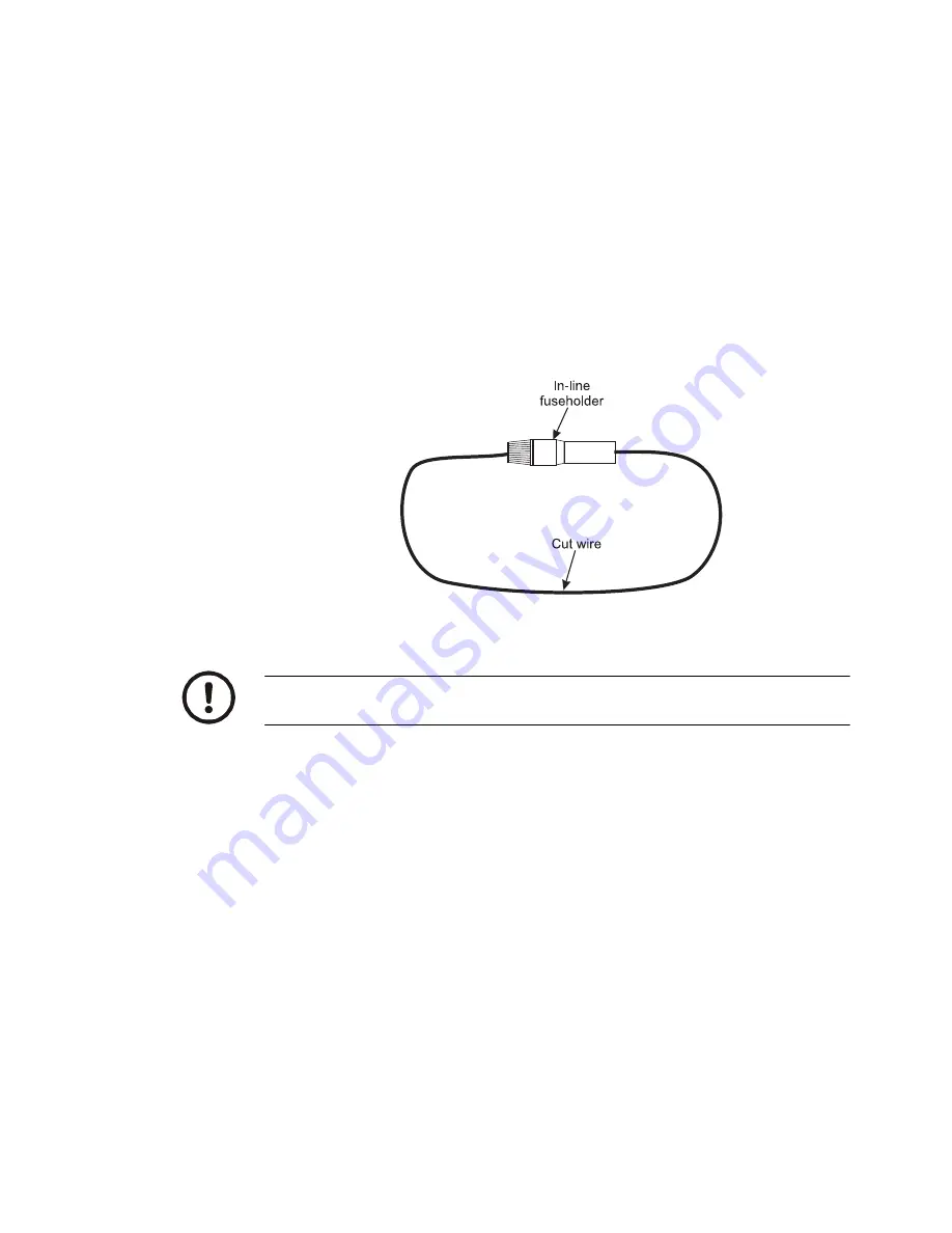
Cut the wire on the fuse holder where indicated in
.
Figure 3.10 Fuse holder
6b.
Using the supplied butt splice connector (item 6 in figure
) and heat shrink
tubing (item 5 in figure
), connect the wire from the fuse holder to the white
wire from the power supply cable. The smaller diameter wire from the power
cable should be inserted into the red striped end of the butt splice connector.
Insert the wire from the fuse holder into the other end (no stripe) of the butt
splice connector. The heat shrink tubing should be placed over the butt splice
connector.
6c.
Cut the heat shrink tubing (item 2 in figure
) in half and place one piece on
the black wire from the power supply cable and one piece on the loose wire
from the fuse holder.
6d.
Crimp the ring terminals (item 1) onto the wires as shown in figure
6e.
Using a heat gun, shrink all three pieces of heat shrink tubing in place.
CAUTION:
Non-approved power connections may damage equipment and void
warranty.


