


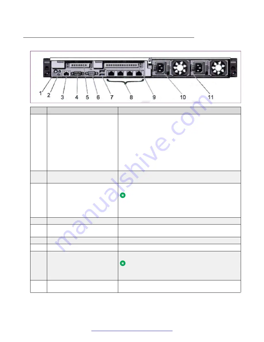
Back view of Dell R620 Server
No.
Item
Description
1
System Identification Button
The identification buttons on the front and back panels can be
used to locate a particular system within a rack. When one of
these buttons is pressed, the LCD panel on the front and the
system status indicator on the back blink until one of the
buttons is pressed again. Press to toggle the system ID on
and off. If the system stops responding during POST, press
and hold the system ID button for more than five seconds to
enter BIOS progress mode.
To reset iDRAC (if not disabled in F2 iDRAC setup), press
and hold for more than 15 seconds.
2
System Identification Connector
The button to connect the optional system status indicator
assembly through the optional cable management arm.
3
iDRAC Enterprise Port
The button for dedicated management port.
Note:
The port is available for use only if the iDRAC7
Enterprise license is installed on your system. (Not
normally used in Avaya systems)
4
Serial Connector
The button to connect a serial device to the system.
5
PCIe Expansion Card Slot 1 (riser
2)
The button to connect a PCIe expansion card.
6
Video Connector
The button to connect a VGA display to the system.
7
USB Connectors (2)
The button to connect USB devices to the system.
8
Ethernet Connectors (4)
Four integrated 10/100/1000 Mbps NIC connectors.
Note:
Dell R620 NIC port numbers are read from left to right,
starting with Port 1, then continuing to port 2, 3, and 4.
9
PCIe expansion card slot 2 (riser
3)
The button to connect a PCIe expansion card.
Table continues…
Hardware overview
22
Deploying Avaya SBCE
August 2015