background image

Verifit

®

User's Guide Version 4.8 

©

 November 2016

Component

Description

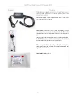
WRECD transducer  

  used to measure the wideband real-ear 

to coupler difference (WRECD) useful in estimating the sound 
level  produced in an individual  ear from measurements in a 
coupler

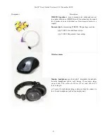
Foam eartips 

for measuring WRECD. The package contains:

Qty 5 ER3-14A adult foam eartips

Qty 5 ER3-14B pediatric foam eartips

Wireless mouse

Monitor headphones  

provided with 2 detachable (detachable 

from the headphone) cables, each having 3.5mm stereo plugs 
on each end. The cables are 130cm  (51 in.) and 365cm  (12 
feet) in length

a 3.5cm to 1/4-inch adapter plug is also provided (to connect to 
the 1/4-inch headphone jack on the display unit)

8

Summary of Contents for verifit

Page 1: ...Audioscan Verifit User s Guide 4 8 November 2016...

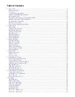
Page 2: ...nnection 30 Printer connection 31 Menus lists and buttons 32 Screen messages and Help 32 Software updating 32 4 General Setup 34 Date and time setup 34 Display settings 34 Saving test setup 34 5 On Ea...

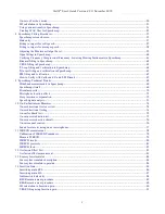
Page 3: ...ails 69 Wideband measurements in Speechmap 69 Speechmap stimuli 69 Stimulus spectra 70 Microphone location effects 72 Deep insertion compensation 72 Speech signal analysis 73 10 On Ear Instrument Meas...

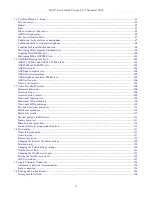
Page 4: ...est 106 Telecoil test results 107 17 Other Test Box Measures 108 Harmonic distortion 108 Noise reduction 108 Noise reduction stimuli 109 Directional function test 109 Directional ITE positioning 110 D...

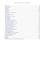
Page 5: ...x curves inconsistent 138 Test box curves differ from specifications 138 Test box speaker overdriven 139 No test box reference mic detected 139 Invalid test box calibration 139 Unable to calibrate tes...

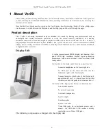
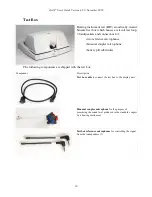
Page 6: ...ystem PEMS The system consists of a real ear measurement REM display unit a hearing instrument test HIT acoustically treated binaural test box and numerous attachable components and accessories Displa...

Page 7: ...th 2 probe microphones which nest into and are connected to the probe dock This is the configuration of these components when they are shipped to you The probe dock has connections for the 2 probe mic...

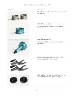
Page 8: ...coupler Foam eartips for measuring WRECD The package contains Qty 5 ER3 14A adult foam eartips Qty 5 ER3 14B pediatric foam eartips Wireless mouse Monitor headphones provided with 2 detachable detacha...

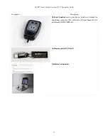
Page 9: ...November 2016 Component Description Tele test handset used to provide an inductive stimulus for simulating operation with a telephone in Speechmap and for performing ANSI TMFS test Audioscan update US...

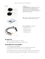
Page 10: ...ophones binaural coupler microphone battery pill substitutes The following components are shipped with the test box Component Description Test box cable to connect the test box to the display unit Bin...

Page 11: ...2cc coupler 1 NOTE for ANSI IEC tests only Not to be used for Speechmap HA 2 BTE 2cc coupler 1 NOTE for ANSI IEC tests only Not to be used for Speechmap Hearing instrument stabilizers attached to the...

Page 12: ...bstitutes kit consisting of 1 E352 Battery Size 10A 1 E353 Battery Size 13A 1 E354 Battery Size 312 1 E355 Battery Size 675 Accessories RE367 36 probe tubes for single patient use 36 per bag ER3 14A a...

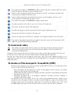
Page 13: ...is not suitable for use in an oxygen rich environment or in the presence of flammable anesthetic mixtures with air or with oxygen or nitrous oxide WARNING To ensure proper operation of this product no...

Page 14: ...h could endanger the environment and human health This product and its associated items must be disposed of in accordance with local disposal regulations for electrical and electronic waste Consult yo...

Page 15: ...ty Service GmbH Schiffgraben 41 30175 Hannover Germany Warranty The Verifit is warranted against defects for two years from date of purchase Within this period it will be repaired without charge for p...

Page 16: ...alia Software licenses Audioscan distributes selected software components under various open source licenses These licenses generally give you the right to copy and change the affected component s sof...

Page 17: ...Verifit User s Guide Version 4 8 November 2016 EC Declaration of Conformity 17...

Page 18: ...DIOSCAN UPDATE STICK IN A SAFE PLACE YOU WILL REQUIRE IT TO INSTALL FUTURE SOFTWARE UPDATES How to Avoid Undesirable Side Effects During the development of the hearing instrument analyzer Audioscan pe...

Page 19: ...are made of soft flexible material specially designed for this application it is possible to scrape the ear canal or touch the eardrum causing brief discomfort You should carefully follow the instruc...

Page 20: ...o a depth greater than 16mm 5 8 3 Remote operation As the Verifit can be run from your PC desktop in On top mode more unconventional office setups are possible as the display unit does not necessarily...

Page 21: ...e test chamber if the test chamber will be used in front to the display unit Note all on ear functions will operate without the test box connected to the display unit Text box cable provided uses HDMI...

Page 22: ...r connector on the rear connector panel 7 Connect the power cord included from the Verifit power supply to a GROUNDED electrical outlet In the USA and Canada this outlet should be marked Hospital Grad...

Page 23: ...dules should be kept in the probe dock when not in use positioned with the reference microphone ports facing outward 3 Link the probe microphone cables with the probe cables adjust clip as shown above...

Page 24: ...ld be cleaned prior to introduction to the test chamber due to the difficulty of sanitizing the acoustic foam Custom hearing instruments must be cleaned with disinfectant towlettes i e audiowipes prio...

Page 25: ...t in use or when transporting the Verifit Mouse and keyboard Failure to follow operating instructions could place the user or operator at risk The Verifit may be operated from a mouse or a standard co...

Page 26: ...ention by selecting only the left or right microphone signals By repeatedly clicking the mouse wheel you rotate your selection among the binaural left only right only and muted headphone presentation...

Page 27: ...d external monitor will operate simultaneously The external monitor must be capable of displaying 1024 x 768 at a refresh rate of 60Hz Ensure that the external display is powered up and set to the cor...

Page 28: ...the power supply module indicates that it is receiving electrical power from the outlet Input device operation The Verifit is operated with a USB mouse included or a keyboard not included to select i...

Page 29: ...Verifit User s Guide Version 4 8 November 2016 The functions of the screen icons and connected keyboard keys are explained in the following table 29...

Page 30: ...s allow the use of a virtual keyboard for entering via mouse only Widgets with this button allow a virtual keyboard to be used Press to show virtual keyboard Not available Press to remove the virtual...

Page 31: ...gh USB or remotely through a computer network Connecting a local printer requires inserting the printer s USB cable into any of the five USB connections available on the side or rear of the display un...

Page 32: ...d item in a drop down option list Screen messages and Help The Title bar top line of the display screen informs you of the selected Test e g Speechmap The Message bar bottom line of the display screen...

Page 33: ...ke the desktop 5 Connect the provided Audioscan update USB stick or any empty USB stick to your computer 6 Double click the audioscan folder then double click audioscan_update 7 Click on Transfer soft...

Page 34: ...blanks the screen to prolong display life click the Screen saver window 3 Select the desired screen saver timing from the drop down list 4 In this screen you can also select the Mouse pointer speed b...

Page 35: ...li and assessment parameters when Erase data is selected 1 Press then click on Save option 2 Click Save test setups on erase data to toggle between Yes and No To set current test levels stimuli and as...

Page 36: ...ne attachment to the AWC which accepts the nozzle of a thin tube or RIC type hearing aid It will also accept the nozzle of the RECD transducer an ER 3A insert earphone and 13 standard earmold tubing W...

Page 37: ...ld be repeated if a probe module is replaced or if a probe tube with different dimensions is installed Switching left and right probe modules after calibration will result in the wrong calibration cur...

Page 38: ...ser s Guide Version 4 8 November 2016 Position the probe tip over the reference microphone Hold probe dock with microphone to be calibrated facing speaker Typical calibration curve Level may be shifte...

Page 39: ...cked against a high quality sound level meter 1 Right click to raise the home menu and click Manual control under On ear 2 Click Level then select 70 from the drop down list 3 Click Frequency then sel...

Page 40: ...lus peak to peak equivalent SPL pe SPL at ABR threshold relative to the average stimulus pe SPL at ABR threshold of a normal hearing jury OR b stimulus SPL at ABR threshold relative to the average sti...

Page 41: ...e for adult females approximately 30 mm from end of probe tube for adult males and approximately 20 25 mm from end of probe tube for children These positions may be modified based on the otoscopic exa...

Page 42: ...November 2016 Probe dock positioned clipped to client clothing adjust clip holding probe microphone modules in place Probe tube insertion the colored lanyard holds the tube in place and the depth mark...

Page 43: ...Insertion gain left click Format then select Graph Table or 2cc targets from the drop down list In 2cc targets format reserve gain and fitting formula may be changed Choose and change reserve gain or...

Page 44: ...w test curve s in all other applications 1 Left click Hide Show 2 Click on the desired test result to toggle between the Hide or Show options The curves will toggle on or off when selected 3 Click wit...

Page 45: ...ting DSL 5 in Speechmap Copyright DSL 2004 Version 5 0 The Desired Sensation Level DSL method is a systematic eardrum sound pressure level SPLogram approach to hearing instrument fitting that seeks to...

Page 46: ...nsertion Gain targets are not provided 2 There is no provision to select Insert earphones earmold as the audiometric transducer since this invalidates the audiometer calibration and correction for thi...

Page 47: ...an accurate SII calculation When using live speech a pause button captures short term speech features See SII calculation in Speechmap and Speechmap Technical Details Before starting please see On Ea...

Page 48: ...imulus click the box beside the stimulus you want to add to the list A check mark will be placed next to the selected stimulus 2 To remove a checked stimulus from the list click the box beside the sti...

Page 49: ...aided screen 1 Max TM SPL change this in Setup 2 Estimated UCL 3 Unaided long term average speech spectrum LTASS 4 Impaired threshold 5 Normal threshold MAP 6 Turn on off display of unaided speech reg...

Page 50: ...4cc coupler are converted to estimated ear canal levels using the RECD or WRECD values age appropriate average entered or measured See Speechmap screen choices In addition the stimulus delivered to t...

Page 51: ...I to speech recognition especially amongst impaired listeners The following shows expected nominal recognition scores vs SII for normals when using a variety of speech stimulus conditions Killion and...

Page 52: ...Choose your custom stimulus After a short delay your stimulus will begin playing 9 Use your new stimulus with all the features of Speechmap Example of two custom files click wav and 1khztone wav in t...

Page 53: ...audio editing software Leveling Options By default Speechmap will automatically level the WAV file so that the SPL matches the level selected for the test The automatic leveling of the WAV file can b...

Page 54: ...Verifit User s Guide Version 4 8 November 2016 Example of user supplied files user wav user_ 4 wav and user_ 2 5 wav 54...

Page 55: ...ar or Test box Graph or Table Dual view or Single view L or R or L R Audiometry BTE HA 4 BTE mold ITE ITC CIC CIC shallow RITE Body Open CROS or FM and Loss simulator Clicking on Audiometry will cause...

Page 56: ...c coupling The WRECD is used to convert 0 4cc coupler SPL measured in the test box to estimated ear canal SPL The WRECD is used to convert entered HL data thresholds and UCL s to ear canal SPL when In...

Page 57: ...quency and level and the ENTER key on the numeric keypad enters or deletes a point The keyboard s numeric keypad can also be used to type in data Switch sides by moving mouse cursor over to other side...

Page 58: ...ap screen choices for setup and audiometric data entry See Using Speechmap 1 Follow the instructions in Speechmap screen choices to enter audiometric data and select the fitting rule 2 Click in the 2...

Page 59: ...clicking beside the Unaided Audibar Adjusting the Maximum Output Level See Speechmap screen choices for setup and audiometric data entry See Using Speechmap Follow the instructions in Speechmap scree...

Page 60: ...There are no special real ear SPL targets for open fittings it doesn t matter how the sound reaches the TM the perception is the same However the sound that escapes from a vent or open fitting may be...

Page 61: ...map from either the On ear or Test box columns 2 Program the hearing instrument so that the frequency lowering feature is inactive 3 Access Test 1 2 3 or 4 by clicking on the appropriate to start that...

Page 62: ...a test The output from both hearing instruments will be display simultaneously 4 Once the test is started click the Stimulus list button to select the stimulus type Click the Level list button and sel...

Page 63: ...ears and turn them ON 2 Position the speaker at 45 degrees to the good ear and set Instrument to BTE 3 Click in test 1 area to start test and record a response using Pink noise at Soft 55 It should be...

Page 64: ...ent to T Telecoil input 2 Click in any of the test areas to start test and select one of the calibrated speech stimuli 3 Change the level to T Loop 65 This will result in a T Loop signal equivalent to...

Page 65: ...Effects The tele test handset can be used in both Test box and On ear Speechmap modes For tests in the test box the lid must remain open while the handset is positioned near the hearing instrument out...

Page 66: ...ng instrument e g like holding a telephone handset or cellphone 6 Activity on the graph indicates that the hearing instrument is receiving the inductive stimulus 7 Click to measure and store the long...

Page 67: ...mitter unmuted repeat step 2 Note that the hearing aid is outside the test box during this test Quiet please The results should be within 2 dB of the results from step 3 If not change FM settings and...

Page 68: ...elow 3 Enable a frequency lowering signal processor Start with the default frequency lowering setting The S will loop so you can keep it playing continuously while you fine tune the frequency lowering...

Page 69: ...International Speech Test Signal ISTS and the single talker International Collegium of Rehabilitative Audiology ICRA distorted speech signal Two speech passages have been filtered to provide the same...

Page 70: ...filtering For fitting FM systems the stimuli may be modified to represent the level 84 dB SPL and spectrum at a chest microphone location and the level 93 dB SPL and spectrum at a boom microphone loca...

Page 71: ...0 1 0 0 0 1 2 5 0 1 6 0 0 2 0 0 0 2 5 0 0 3 1 5 0 4 0 0 0 5 0 0 0 6 3 0 0 8 0 0 0 1 0 0 0 0 1 2 5 0 0 1 6 0 0 0 Fre q u e n cy H z 1 3 o ct a v e b a n d SP L fo r sp e e ch a t 7 0 d B SP L fro m B y...

Page 72: ...3 9 11 9 27 7 10000 40 4 28 0 34 1 31 4 52 2 7 1 2 3 10 7 26 5 12500 38 2 22 6 31 3 29 9 52 2 10 6 3 1 9 7 25 5 Overall 65 65 65 65 65 75 75 84 93 The above values may differ slightly from previous s...

Page 73: ...trum for each of a series of short time periods within the passage Historically time periods of 120 125 or 128 ms have been used The Verifit uses a 128 ms time period resulting in 100 levels or sample...

Page 74: ...ing aids Once directional performance is observed the test may be terminated Because this measurement is carried out in a real room results are not expected to agree with data taken in large anechoic...

Page 75: ...to advance the probe tube further into the ear canal A lubricant applied in the vicinity of the probe tube will ease insertion and prevent slit leaks 2 Set the instrument as it will be used with feedb...

Page 76: ...n example of the noise created by a household air conditioner Vacuum is a sample of noise from th operation of a vacuum cleaner on a carpeted floor Multi talker Babble is the combination of ten differ...

Page 77: ...s measured by the probe and reference microphones A and C weighted measurements are limited to frequencies above 100 Hz and the averaging time and update rate are 384 ms 1 Refer to On Ear Measures Set...

Page 78: ...tion of the Audioscan RECD transducer in this coupler is required at a minimum of weekly 1 Connect the WRECD transducer to the WRECD jack on the Probe Dock Prepare the system for test box tests See Mi...

Page 79: ...o to 15 3 Calibration of WRECD transducer If a valid transducer calibration exists select Measure real ear 4 Couple a standard insert earphone foam eartip to the nozzle of the WRECD transducer If usin...

Page 80: ...essed WRECD from the main menu you may click the Age box to change the age for this reference curve WRECD results The WRECD measurement screen shows the response of the WRECD transducer in the 0 4cc c...

Page 81: ...the measurement in the test box Measured WRECD is appropriate for coupler simulation and error is minimized Alternate method 1 RECD On ear measurement Audioscan WRECD transducer client s personal earm...

Page 82: ...differs for the ear canal and 2cc coupler measurements further RECD differences will result The Verifit requires RECD data up to 12 5 kHz to facilitate wideband testing and as a result RECD has been r...

Page 83: ...aints This occlusion effect measurement is useful in quantifying the extent to which venting or deep insertion is addressing the underlying cause of the complaint Occlusion effect measurement 1 Refer...

Page 84: ...ll damage Any loss greater than this is considered inner hair cell loss This SLS does not simulate broadening of the auditory filters or other distortions that may accompany cochlear hearing loss To p...

Page 85: ...9 Click Type of loss to toggle between Sensorineural and Conductive hearing loss simulations 10 Click or to stop the demonstration and freeze the stimulus speech banana on the screen 11 Click on to e...

Page 86: ...ts Speechmap is recommended for fitting all linear and non linear hearing instruments Refer to On Ear Measures Setup and On Ear Measures Screen Setup for terminology and information on preparing the s...

Page 87: ...k the right mouse button and then select Insertion gain 2 Click Instrument to chose from BTE ITE ITC CIC CROS Body This changes the CORFIG used for 2cc targets 3 Click the fitting method button to cho...

Page 88: ...ion 70 dB SPL 5 Target Aided Threshold 6 Unaided Threshold 7 Estimated Aided Threshold Audiometric data entry Threshold data and parameters may be entered by manually using a mouse or the numeric keyp...

Page 89: ...verage See Audiometric data entry 1 Click the right mouse button and then select Insertion gain 2 Referring to On Ear Measures Setup and On Ear Measures Screen Setup prepare the system position the pa...

Page 90: ...nt If no level is shown use the lowest level required to overcome background noise 8 Adjust the hearing instrument so that the REIG curve SPL scale or Aided threshold curve HL scale approximates the d...

Page 91: ...on in the ears and turn them ON 2 Position the speaker at 45 degrees to the good ear and set Instrument to BTE 3 Select REAR 1 and record a response using Pink noise at 55 It should be like a normal...

Page 92: ...Verifit User s Guide Version 4 8 November 2016 92...

Page 93: ...may be hidden but not erased Test box screen Except for Input Output Battery drain and Manual control screens you have the option of selecting either a single full screen view or a dual side by side...

Page 94: ...Verifit User s Guide Version 4 8 November 2016 94...

Page 95: ...e test screen you have the option of displaying test results in SPL dB or gain dB To change the scale click dB SPL or dB Gain Hide or Show test box curves To hide or show unaided and aided curves on t...

Page 96: ...I S3 22 2003 and ANSI S3 22 2009 facts The Frequencies feature allows hearing instruments to be evaluated at the Special Purpose Average SPA frequencies defined by ANSI S3 22 rather than the default H...

Page 97: ...ion curve should be similar to the one shown but may be at a different level It should remain stable over time Irregularities in the calibration curve may be the result of not properly aligning the mi...

Page 98: ...microphone See Calibrating test box reference microphone 2 Screw the appropriate calibrator ring onto the coupler microphone 3 Insert the coupler microphone with the attached calibrator ring into the...

Page 99: ...or block the sound outlet of the mold Vents should be sealed at the lateral end It is very important that the instrument be well sealed to the coupler Use the hearing instrument stabilizers to prop th...

Page 100: ...amination hearing instruments should be clean before putty is applied and putty should be replaced frequently The Verifit is supplied with two blue colored metal 2cc couplers a type HA 1 ITE and a typ...

Page 101: ...sing the TRIC adapter except where otherwise required by the hearing instrument manufacturer Excess low frequency output is usually due to open vents or a poor seal to the coupler For health reasons h...

Page 102: ...Verifit User s Guide Version 4 8 November 2016 Positioning an ITE instrument for ANSI tests Positioning a RIC instrument for ANSI tests 102...

Page 103: ...ht mouse button to raise the home menu then select ANSI for ANSI 2003 or ANSI IEC for ANSI 2009 depending on what has been selected in Setup 2 Click Start test and follow the test setup instructions w...

Page 104: ...any setting of the instrument controls but ANSI S3 22 requires that certain settings be used See ANSI S3 22 2003 and ANSI S3 22 2009 facts The Input Output test allows you to generate up to 4 separat...

Page 105: ...ies RSETS relative simulated equivalent telephone sensitivity is calculated as HFA SPLITS minus RTG 60 A positive RSETS indicates greater output when using the telephone than when using the microphone...

Page 106: ...l be shown ANSI test loop test ANSI S3 22 requires that the gain control be set to RTS before running this test The reference test gain RTG is required in order to calculate the RTLS The easiest way t...

Page 107: ...Verifit User s Guide Version 4 8 November 2016 Telecoil test results 107...

Page 108: ...aise home menu and select Distortion under Test box 2 Refer to Coupling the hearing instrument Positioning the hearing instrument and Battery pill use and care to prepare the instrument 3 Turn the hea...

Page 109: ...edback compensation and other non linear algorithms Speech is added as a conditioning signal to ensure automatic speech activated directional programs become active Test levels are selectable in 5 dB...

Page 110: ...t the front microphone opening on the faceplate and seal any vent at the faceplate Other positions may be preferable for some instruments Directional BTE positioning Ensure that the left hearing instr...

Page 111: ...n curve the response to the back speaker s signal For a non directional instrument the two curves will be nearly identical Setting the instrument for directional operation should produce a separation...

Page 112: ...Setup for connecting the hearing instrument to the coupelr microphone 3 Ensure the hearing instrument is powered and turned on 4 Select test 1 2 3 or 4 by pressing the respective button 5 Select Stimu...

Page 113: ...octave frequencies Pressing Continue causes the swept filter analysis to be performed in 1 12th octave bands and displayed at 1 12th octave frequencies Battery drain test The battery drain test automa...

Page 114: ...upler is not useful at high frequencies because of resonances and low signal levels The use of the AWC is desirable because it raises the high frequency SPL of the hearing aid by more than 20 dB makin...

Page 115: ...the home menu using the right mouse button Select Manual control from the Test box list 2 Click on the Level button and select 0 dB stimulus level from the drop down list 3 Click on the Filter button...

Page 116: ...Verifit User s Guide Version 4 8 November 2016 extension cables should not be used They will substantially increase noise levels 116...

Page 117: ...ts wireless or wired interface The Verifit supports the 802 11 b g or n wireless network standards and speeds as well as the following wifi security standards 2 WPA WPA2 Passphrase Most common 3 WEP 1...

Page 118: ...k WLAN a Select Change to set Network to the Wireless option b Click Scan c The Wireless Network poster will be presented and the Verifit will automatically scan for available wireless networks Note n...

Page 119: ...imes use static address assignment Ask your network administrator for help in performing the following steps 7 To assign a static network address a Disable Auto DHCP b Click the Change button c Enter...

Page 120: ...s including 5900 The presence of such security measures may require changing the rule within the anti virus package to allow the Audioscan Remote application to run properly TeleAudiology Once your Ve...

Page 121: ...he Audioscan TeleAudiology application NOAH Service Port Consult your Network Administrator before changing the NOAH service port Changing the port successfully requires understanding the security pol...

Page 122: ...1 86 8080 noah 2 If the communication is successful the web browser will display NOAH data formatted in XML noah Example XML noah Web Service Port The Verifit provides a simple web server for retriev...

Page 123: ...Verifit User s Guide Version 4 8 November 2016 123...

Page 124: ...rk connector on the PC 3 On the Verifit right click select and then click Network 4 Select Change to set Network to the Wired option Ensure Auto use DHCP is checked and click Test connection A network...

Page 125: ...the Subnet mask box 6 On the Verifit un check Auto on the Setup network screen and click the Change button Then set the network addresses as shown below by clicking on the down arrow buttons and selec...

Page 126: ...n the HIMSA NOAH public data format then they can also be obtained from or exchanged with other NOAH modules that comply with the public standard For example the Verifit can restore audiograms from an...

Page 127: ...oose Windows Share if the printer connects through a Windows laptop PC or server computer Windows shared printers are common in both small and large offices See the section below Windows shared printe...

Page 128: ...printer to start printing the test page Otherwise check your settings and try again Alternatively you may prefer to use a web browser to capture the Verifit screen image and to print from the browser...

Page 129: ...results in a file for future printing and viewing You can also include these printed files in documents or display them in presentations In Printing Setup select the File output option To save the out...

Page 130: ...he page setup Header and Date To include custom text in the header enable the Header checkbox and enter the text in the field below it To include the date and time of printing in the header enable the...

Page 131: ...ion If the network connection fails the will Verifit present the Network setup details where you can correct any setup problems before trying again See the section Network Setup for details With a suc...

Page 132: ...wing table indicates the possible causes of each failure and the corrective steps Failure Cause Correction Server The server cannot be found in the specified domain Change the server Change the domain...

Page 133: ...marked with a green check and the printer will print the setup details on a sheet of paper Network printer details Printer test passed Web browser screen capture You can capture the Verifit screen im...

Page 134: ...s on a USB drive or on a Windows shared folder You can later restore the session files to the same Verifit or to other Audioscan equipment Since the files use an XML data format you can also view sess...

Page 135: ...urity Rule To store a session file 1 Click Session 2 Select Store session to file 3 Click the Client ID list button This will display a list of Client IDs with the first entry highlighted To add a new...

Page 136: ...Excel To view a session file Excel right click on the file and select Open With Choose a browser program or Microsoft Excel When prompted for a style sheet select the audioscan xsl from the same folde...

Page 137: ...hen click on Self test 2 If you received a Max out in or a Routing failure remove any hearing aids from the test chamber and rerun self test 3 Unplug probe dock from display unit and unplug both the t...

Page 138: ...equipment on the same table or wooden floor Computers fans and air conditioners may be the source of the vibration Try turning off suspected sources to identify the cause Relocate the source or the V...

Page 139: ...box reference microphone Plug the microphone back in again ensuring that it clicks into place Try the calibration procedure again Try switching the right and left test box reference microphones Invali...

Page 140: ...faulty microphone Ensure not to attempt to use cleaned or sterilized probe tubes as this causes the probe mic inlet tube to become clogged with cerumen requiring microphone replacement and voiding mi...

Page 141: ...ap when running in L R mode in the testbox It indicates that there was a significant difference between the left and right reference microphones Check that both reference microphones are securely plug...

Page 142: ...is currently under test Headphone high distortion or noise Headphone output contains uncomfortable distortions or noise Headphone output may be clipping when using a high powered hearing instrument Re...

Page 143: ...isplay unit 3 0 kg 6 6 lb Test box 4 0 kg 8 8 lb Shipping 14 9 kg 32 8lb Display type LED backlit active color Display size 12 1 diagonal Resolution 1024x768 XGA Stereo headphone monitor amplifier 250...

Page 144: ...dB SPL 8000 12500 Hz 4 dB SPL Equalization method Real time modified pressure method Stored for open fittings Analysis Frequencies per octave 12 Filter bandwidth 1 12th octave Measurement accuracy for...

Page 145: ...oupler SPL Telephone Simulator Simulated Telecoil Sensitivity Battery Drain OTHER TESTS AVAILABLE Speechmap Speechmap for fitting telecoils Real time adaptive directional verification Frequency loweri...

Page 146: ...s Swept tone frequencies per octave 12 Burst tone frequencies per octave 3 Speech Noise filter 1 3 octave Measurement accuracy for tones 1kHz 1 dB re 1 kHz 200 5000 Hz 1 dB re 1 kHz 5000 8000 Hz 2 5 d...

Page 147: ...nd distortion FITTING METHODS AVAILABLE Speechmap with DSL5 2 NAL NL1 NAL NL2 CAMFIT Insertion gain with NAL RP NAL NL1 Fig6 Pogo II Berger Libby Sensory Loss Simulator Simulation types Sensorineural...

Page 148: ...Verifit User s Guide Version 4 8 November 2016 148...

Page 149: ...Verifit User s Guide Version 4 8 November 2016 149...

Page 150: ...ion of input level duration and frequency CROS Contralateral Routing Of Signals a type of hearing aid in which the microphone is at the ear opposite to the one receiving the amplified sound CORFIG cou...

Page 151: ...value of the total signal may be used instead of the fundamental HFA High Frequency Average the average of values in dB at 1000 1600 and 2500 Hz ANSI S3 22 HL Hearing Level the hearing threshold refer...

Page 152: ...requency a sinusoidal acoustic signal 1 REAG Real Ear Aided Gain difference in dB as a function of frequency between the SPL or BSPL at a specified measurement point in the ear canal and the SPL or BS...

Page 153: ...oduced by Audioscan in 1992 It presents hearing threshold UCL and amplified speech spectra as SPL in the ear canal The fitting goal is to make amplified speech audible and comfortable while avoiding d...

Page 154: ...a specified stimulus that is judged to be definitely uncomfortable Volume Control a user operated gain control Wideband the extension of the frequency response bandwidth from 8kHz to 16kHz WRECD Wideb...

Page 155: ...an K et al 1994 An international comparison of long term average speech spectra Journal of the Acoustical Society of America vol 96 No 4 Oct 1994 2108 2120 Byrne D 1977 The speech spectrum Some aspect...

Page 156: ...to coupler differences in children with grommets British Journal of Audiology 31 63 69 McInerney C Tang J Zelmer D Scollie S 2016 Development of a Cantonese Speech Passage for Hearing Aid Evaluation...

Page 157: ...aracteristics for young hearing impaired children Ear and Hearing 6 1 48 53 Seewald R C Ross M Stelmachowicz P G 1987 Selecting and verifying hearing aid performance characteristics for young children...

Page 158: ...Verifit User s Guide Version 4 8 November 2016 25 Appendix 1 Manufacturer Disclosure Statement for Medical Device Security 158...

Page 159: ...Verifit User s Guide Version 4 8 November 2016 159...

Reviews: