Version 6.2
665
February 2011
SIP User's Manual
12. Configuration Parameters Reference
12.3 Debugging and Diagnostics Parameters
This subsection describes the device's debugging and diagnostic parameters.
12.3.1 General Parameters
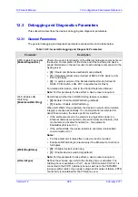
The general debugging and diagnostic parameters are described in the table below.
Table
12-12: General Debugging and Diagnostic Parameters
Parameter
Description
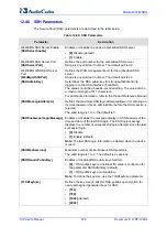
EMS: Enable Diagnostics
[EnableDiagnostics]
Checks the correct functionality of the different hardware components on
the device. On completion of the check and if the test fails, the device
sends information on the test results of each hardware component to the
Syslog server.
[0]
= Rapid and Enhanced self-test mode (default).
[1]
= Detailed self-test mode (full test of DSPs, PCM, Switch, LAN,
PHY and Flash).
[2]
= A quicker version of the Detailed self-test mode (full test of
DSPs, PCM, Switch, LAN, PHY, but partial test of Flash).
For detailed information, refer to the
Product Reference Manual
.
Note:
For this parameter to take effect, a device reset is required.
Web: Enable LAN
Watchdog
[EnableLanWatchDog]
Determines whether the LAN Watch-Dog feature is enabled
.
[0]
Disable = Disable LAN Watch-Dog (default).
[1]
Enable = Enable LAN Watch-Dog.
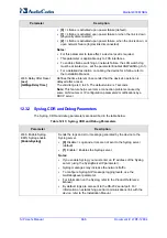
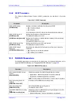
When LAN Watch-Dog is enabled, the device's overall communication
integrity is checked periodically. If no communication is detected for
about three minutes, the device performs a self test:
If the self-test succeeds, the problem is a logical link down (i.e.,
Ethernet cable disconnected on the switch side) and the Busy Out
mechanism is activated if enabled (i.e., the parameter
EnableBusyOut is set to 1).
If the self-test fails, the device restarts to overcome internal fatal
communication error.
Notes:
For this parameter to take effect, a device reset is required.
Enable LAN Watchdog is relevant only if the Ethernet connection is
full duplex.
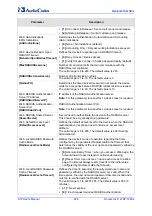
[WatchDogStatus]
[0]
= Disable device's watch dog.
[1]
= Enable device's watch dog (default).
Note:
For this parameter to take effect, a device reset is required.
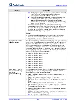
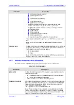
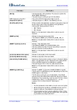
[LifeLineType]
Defines the scenario upon which the Lifeline phone is activated. The
Lifeline phone is available on Port 1 of each FXS module.FXS Port 1 is
connected to the POTS (Lifeline) phone as well as to the PSTN/PBX
(using a splitter cable). Upon power outage and/or network failure, PSTN
connectivity is maintained for the FXS phone user.
Summary of Contents for Mediant 800 MSBG
Page 2: ......
Page 366: ...SIP User s Manual 366 Document LTRT 12804 Mediant 800 MSBG Reader s Notes ...
Page 372: ...SIP User s Manual 372 Document LTRT 12804 Mediant 800 MSBG Reader s Notes ...
Page 390: ...SIP User s Manual 390 Document LTRT 12804 Mediant 800 MSBG Reader s Notes ...
Page 404: ...SIP User s Manual 404 Document LTRT 12804 Mediant 800 MSBG Reader s Notes ...
Page 616: ...SIP User s Manual 616 Document LTRT 12804 Mediant 800 MSBG Reader s Notes ...
Page 636: ...SIP User s Manual 636 Document LTRT 12804 Mediant 800 MSBG Reader s Notes ...
Page 652: ...SIP User s Manual 652 Document LTRT 12804 Mediant 800 MSBG Reader s Notes ...
Page 886: ...SIP User s Manual 886 Document LTRT 12804 Mediant 800 MSBG Reader s Notes ...

