47
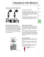
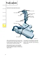
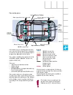
Components
G
Fuel gauge sender
G1
Fuel gauge
G6
Fuel pump
G169
Fuel gauge sender 2
J17
Fuel pump relay
J218
Combi processor in dash panel insert
J220
Motronic control unit 2
S
Fuse
The senders can be accessed via
two openings below the rear
seat.
For removing and installing the
senders, please follow the
instructions given in the Work-
shop Manual.
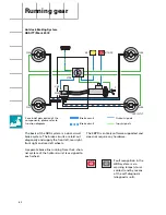
The tank senders are connected in series.
R
1
+ R
2
= R
total
Signals are evaluated in the dash panel insert
microprocessor.
Electrical circuit
SSP207/121
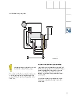
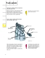
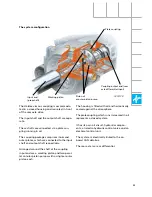
The fuel lines and left-hand tank sender are
connected to the baffle housing in the tank.
The suction jet pump is driven by the two-
stage fuel pump.
The suction jet pump can only be removed
after de-taching the fuel lines and tank sender
from the baffle housing.
SSP207/82
M
30
15
X
31
J220
30
15
X
31
G6
G1
J218
J17
S
31
31
G
G169

