20
Zone settings
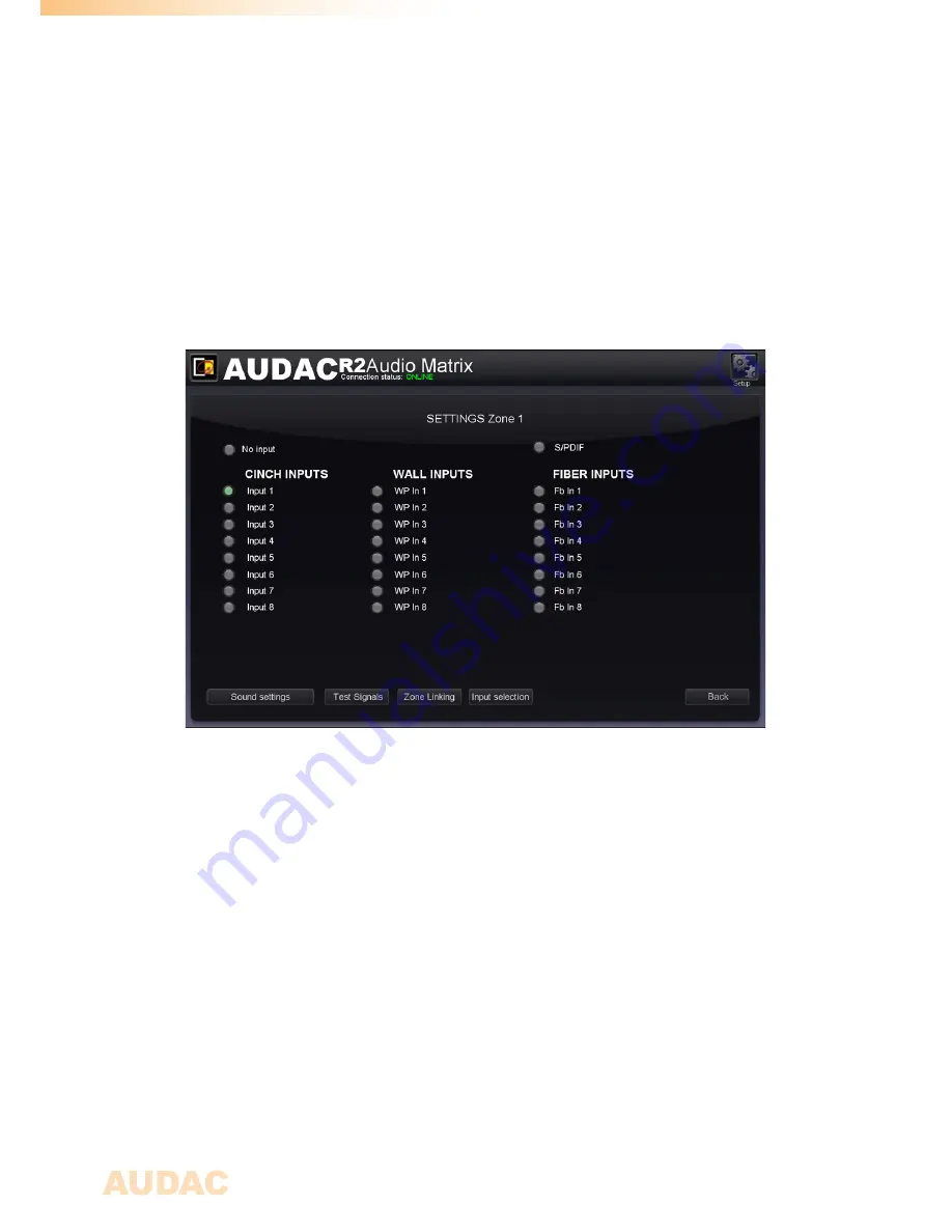
After clicking on a “Settings” button, displayed by a fader of a specific zone, you will
be redirected to the “Zone Settings” window. This window gives an overview of all the
settings that can be applied to one specific zone.
Zone settings
Input channel selection
The first window gives an overview of all input channels which can be patched to that
particular output zone. The first displayed option is ‘No Input”, which means when this
option is selected, no input signal will be routed to that particular output zone. At the same
level is the S/PDIF selection button displayed.
Below are from left to right the “Cinch inputs”, the “Wall inputs” and the “Fiber inputs”
displayed.
The “Cinch Inputs” are the direct line inputs which are provided on the rear panel of the
R2 by means of RCA connectors. In the second table are the “Wall Inputs” displayed.
These are all additional input signals (Line or Microphone) which are connected to an
optional wall input unit (DW5066) inputs on the rear side of the R2. In the third table are
the “Fiber Inputs” displayed (Only functional when the optional OPT2 module is installed).
These are the digital audio channels which are transferred over the fiber interconnection
interface, and can be patched to the selected output zone.
To select the desired audio input source which has to be patched with the selected output
channel, simply click the button next to the desired input source. The selected input signal
selection screen” menu, which can be obtained by clicking the “Settings” button below
the “Input Selection” dropdown list. In this case, the option “Other” will appear.
Configuration menu
In the top right corner is a “Setup” button displayed. After clicking this button, you will be
redirected to the general configuration menu of the R2.
Summary of Contents for R2
Page 1: ...R2 User Manual www audac eu ...
Page 2: ...2 ...
Page 8: ...8 ...
Page 58: ...58 Notes ...
Page 59: ...59 Notes ...
Page 60: ...60 Notes ...


