


CHAPTER 4: INSTALLATION
4-2
DigiVu
®
Series Multichannel MPEG-2/H.264 Encoder/Multiplexer with QAM &/or IP Output - Installation & Operation Manual
4.3.3 Conductor Termination
Termination of the supplementary equipment grounding conductor may be made to building steel, to a metal electrical raceway
system, or to any grounded item that is permanently and reliably connected to the electrical service equipment earth.
4.3.4 Conductor Type
Bare, covered or insulated grounding conductors are acceptable. A covered or insulated grounding conductor shall have a
continuous outer finish that is either green, or green with one or more yellow stripes.
4.4 RF Cable Sheath Grounding
4.4.1 Requirement to Ground the Coaxial Cable Sheath
In addition to the supplementary ground to the equipment, it is also required to ground the sheath of the RF coaxial cable at
it’s point of entrance to the building. If the chassis is installed at a location removed from the point of coaxial cable entrance,
it is the installer’s responsibility to ensure that the grounding of the sheath has already been performed in accordance with
electrical code directives.
4.4.2 Size of Grounding Conductor
The size of grounding conductor and the manner of attachment to the coaxial cable should be in accordance with the national
electrical safety regulations in effect in the country in which the installation is located.
4.4.3 Minimize Coaxial Cable Sheath Currents
Care should be taken when grounding the coaxial cable sheath to ensure that circulating currents are minimized to prevent
interference on the RF signal. This ground loop condition may be minimized by connecting the coaxial cable sheath grounding
conductor to the same building ground point as the chassis safety ground conductor attachment.
4.5 Mounting
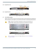
4.5.1 Rack Mounting
The chassis is intended to be mounted in a standard 19” EIA equipment rack. A reasonable amount of space will be required
in front of and behind to allow installation and servicing. The equipment is designed with fan forced cooling which exhausts
to the top and side of the unit. Avoid blocking airflow at the top and sides and mount in such a manner to provide a source of
ambient cool air at the front fan air intake grill. Provide at least one open rack space above the chassis. Consider also that the
site technician will need access to the front and back of the unit for accessing connections, maintenance and configuration
when determining the best mounting location.
4.5.2 Mounting Precautions
FYI:
See
“Equipment Safety Grounding” on page 4-1
for detailed information on grounding.
1. Elevated Operating Ambient:
If installed in a closed environment that may exceed room ambient temperature, consideration should be given to
installing the equipment in an environment compatible with the maximum ambient temperature specified (50°C).
2. Reduced Air Flow:
Installation should allow at least 2” spacing around the equipment to ensure that airflow required for proper operation
is not compromised. At least one blank rack space above the unit should be allowed.
3. Mechanical Loading:
Mounting of the equipment should be according to the installation instructions so that a hazardous condition is not
created due to improper mechanical loading. Do not use the DigiVu to mechanically support other equipment.
4. Circuit Overloading:
Consideration should be given to the connection of the equipment to the supply circuit and the effect that overloading
of the circuit will have on over-current protection and supply wiring. Consider equipment nameplate ratings when
addressing this concern.
5. Reliable Earthing:
The chassis must be connected to a reliable ground or earth connection with an adequately sized copper conductor.
See


