ATLAS North America Proprietary
Sea Scan ARC Scout MKII Operations Manual
1 of 1
Page: 17
Issue: 1.2.4
SCTM2-OPS
Operations Manual
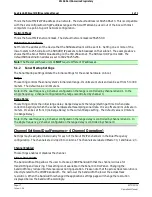
This is the Scout MkII's IPV4 address on a network. The default address is 169.254.86.213. This is compatible
with the zeroconfig/autoconfig IP address range so the Scout MkII can be used out of the box with most
computers in a point-to-point network configuration.
Network Mask
This is the Scout MkII's network mask. The default network mask is 255.255.0.0.
SDS Destination Address
Set this to the address of the device that the SDS data stream will be sent to. Setting one or more of the
lower octets to 255 will allow the SDS UDP/IP packets to be broadcast on that subnet. The example above
shows that the Scout MkII is broadcasting on the 169.254 subnet. The SDS over UDP port is 1409. The
default SDS destination address is set to 169.254.255.255.
Note:
The Master and Slave units do
NOT
require different IP addresses.
5.1.2
Sonar Startup Settings
The Sonar Startup settings dictate the initial settings for the sonar hardware on boot.
Range
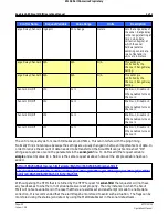
This setting controls the sonar system's initial slant range. Its units are meters and can be set from 5 to 300
meters. The default value is 30 meters.
Note: In the dual frequency, 4 channel configuration the range is controlled by channels 0 and 1. In the
single frequency, 2 channel configuration the range is controlled by channel 0.
Range Delay
This setting controls the initial range delay. Range delay sets the range (starting at time 0 when data
collection begins) at which the sonar hardware starts sampling sonar data. It is an offset and its units are in
meters. It can be set from 0 (no Range Delay) to the current Range setting. The default value is 0 meters
(no Range Delay).
Note: In the dual frequency, 4 channel configuration the range delay is controlled by channels 0 and 1. In
the single frequency, 2 channel configuration the range delay is controlled by channel 0.
Channel Settings (Dual Frequency - 4 Channel Operation)
Settings may be adjusted individually for each of the Scout MkII's 4 channels in the Dual Frequency
configuration. The channels are divided into columns. The channels are labeled Master: 0, 1 and Slave: 2, 3.
Channel Enabled
This settings enables or disables the channel.
Channel Bandwidth
The bandwidth setting allows the user to choose a CHIRP bandwidth that the channel will use for
transmitting and receiving. This setting is not available in the Sonar Control Panel. Changing the
bandwidth may reduce interference issues during operation. Please note that the across track resolution is
directly related to the CHIRP bandwidth. The narrower the bandwidth the lower the across track
resolution. When the bandwidth is changed the application settings page will change the resolution
displayed below the bandwidth accordingly.

