


2-36
Chapter 2: Hardware information
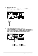
10. System panel connector (20-pin PANEL1)
This connector supports several chassis-mounted functions.
1. System power LED (3-pin PLED)
This 3-pin connector is for the system power LED. Connect the chassis
power LED cable to this connector. The system power LED lights up
when you turn on the system power, and blinks when the system is in
sleep mode.
2. Message LED (2-pin MLED)
This 2-pin connector is for the message LED cable that connects to
the front message LED. The message LED is controlled by Hardware
monitor to indicate an abnormal event occurance.
3. System warning speaker (4-pin SPEAKER)
This 4-pin connector is for the chassis-mounted system warning
speaker. The speaker allows you to hear system beeps and warnings.
4. Hard disk drive activity LED (2-pin HDDLED)
This 2-pin connector is for the HDD Activity LED. Connect the HDD
Activity LED cable to this connector. The IDE LED lights up or flashes
when data is read from or written to the HDD.
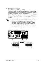
5. Proprietary power button/soft-off button (2-pin PWRSW)
This connector is for the system power button. Pressing the power
button turns the system on or puts the system in sleep or soft-off mode
depending on the BIOS settings. Pressing the power switch for more
than four seconds while the system is ON turns the system OFF.
6. Reset button (2-pin RESET)
This 2-pin connector is for the chassis-mounted reset button for system
reboot without turning off the system power.
Summary of Contents for Z8NH-D12
Page 1: ...Motherboard Z8NH D12 Series Z8NH D12 Z8PH D12 IFB Z8PH D12 SE QDR ...
Page 24: ...2 6 Chapter 2 Hardware information 2 2 4 Motherboard layouts Z8NH D12 ...
Page 25: ...ASUS Z8NH D12 Series 2 7 Z8PH D12 IFB ...
Page 26: ...2 8 Chapter 2 Hardware information Z8PH D12 SE QDR ...
Page 56: ...2 38 Chapter 2 Hardware information ...
Page 100: ...4 40 Chapter 4 BIOS setup ...
Page 167: ...ASUS Z8NH D12 Series 6 33 8 Click your preferred options and click Finish to exit the wizard ...
Page 175: ...ASUS Z8NH D12 Series A 3 A 1 Z8NH D12 block diagram ...
Page 176: ...A 4 Appendix A Reference information A 2 Z8PH D12 IFB block diagram ...
Page 177: ...ASUS Z8NH D12 Series A 5 A 3 Z8PH D12 SE QDR block diagram ...