


2-10
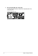
Chapter 2: Hardware information
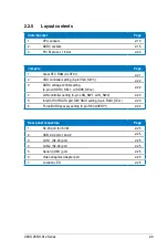
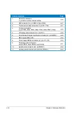
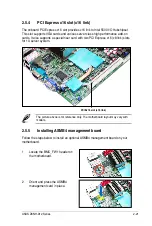
Internal connectors
Page
1.
Serial ATA connectors
(7-pin SATA1, SATA2, SATA3, SATA4)
2-26
2.
USB connector (5-1 pin USB3, A-Type USB4)
2-27
3.
Thermal sensor cable connectors (3-pin TR1, TR2)
2-27
4.
Front fan connectors
(4-pin FRNT_FAN1, FRNT_FAN2, FRNT_FAN3, FRNT_FAN4)
2-28
5.
LPC debug card connector (14-1 pin LPC1)
2-29
6.
Serial General Purpose Input/Output connector (6-1 pin SGPIO1)
2-29
7.
BMC header (BMC_FW1)
2-30
8.
Power Supply SMBus connectors (6-1 pin JP1; JP2)
2-30
9.
Proprietary power connectors
(20-pin PWR1, 20-pin PWR2, 4-pin PWR3)
2-31
10.
System panel connector (20-1 pin PANEL1)
2-32
11.
Auxiliary panel connector (20-2 pin AUX_PANEL1)
2-33
Summary of Contents for Z8NH-D12
Page 1: ...Motherboard Z8NH D12 Series Z8NH D12 Z8PH D12 IFB Z8PH D12 SE QDR ...
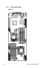
Page 24: ...2 6 Chapter 2 Hardware information 2 2 4 Motherboard layouts Z8NH D12 ...
Page 25: ...ASUS Z8NH D12 Series 2 7 Z8PH D12 IFB ...
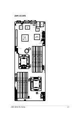
Page 26: ...2 8 Chapter 2 Hardware information Z8PH D12 SE QDR ...
Page 56: ...2 38 Chapter 2 Hardware information ...
Page 100: ...4 40 Chapter 4 BIOS setup ...
Page 167: ...ASUS Z8NH D12 Series 6 33 8 Click your preferred options and click Finish to exit the wizard ...
Page 175: ...ASUS Z8NH D12 Series A 3 A 1 Z8NH D12 block diagram ...
Page 176: ...A 4 Appendix A Reference information A 2 Z8PH D12 IFB block diagram ...
Page 177: ...ASUS Z8NH D12 Series A 5 A 3 Z8PH D12 SE QDR block diagram ...