
Chapter 5: BIOS Setup
5-20
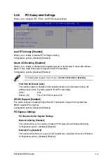
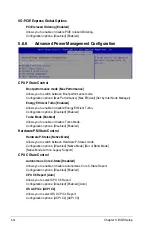
PCI Express GEN2 Device Register Settings
Target Link Speed [Auto]
If supported by hardware and set to Force to X.X GT/s, for Downstream Ports, this sets
an upper limit on Link operational speed by restricting the values advertised by the
Upstream component in its training sequences. When Auto is selected HW initialized
data will be used.
Configuration options: [Auto] [Force to 2.5 GT/s] [Force to 5.0 GT/s] [Force to 8.0 GT/s]
Clock Power Management [Disabled]
If supported by hardware and set to Enabled, the device is permitted to use CLKREQ#
signal for power management of Link clock in accordance to protocol defined in
appropriate form factor specification.
Configuration options: [Disabled] [Enabled]
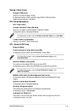
Compliance SOS [Disabled]
If supported by hardware and set to Enabled, this will force LTSSM to send SKP
Ordered Sets between sequences when sending Compliance Pattern or Modified
Compliance Pattern.
Configuration options: [Disabled] [Enabled]
Hardware Autonomous Width [Enabled]
If supported by hardware and set to Disabled, this will disable the hardware’s ability to
change link width except for width size reduction for the purpose of correcting unstable
link operation.
Configuration options: [Disabled] [Enabled]
Hardware Autonomous Speed [Enabled]
If supported by hardware and set to Disabled, this will disable the hardware’s ability
to change link speed except for speed rate reduction for the purpose of correcting
unstable link operation.
Configuration options: [Disabled] [Enabled]
PCIE OPROM Slot Options
PCIE1 Slot OpROM [Enabled]
This option allows you to enable or disable the OpROM of the PCIe slots.
Configuration options: [Disabled] [Enabled]
Summary of Contents for RS720Q-E9-RS8
Page 1: ...2U Rackmount Server RS720Q E9 RS8 User Guide ...
Page 12: ...xii ...
Page 45: ...2 21 RS720Q E9 RS8 Series RS720Q E9 RS8 Upper Mid Plane Lower Mid Plane Backplane ...
Page 56: ...Chapter 4 Motherboard Information 4 2 4 1 Motherboard and Mid plane layout Z11PH D12 ...
Page 57: ...4 3 RS720Q E9 RS8 Series RS720Q E9 RS8 S Mid Plane RS720Q E9 RS8 Mid Plane ...
Page 72: ...Chapter 4 Motherboard Information 4 18 ...
Page 118: ...Chapter 5 BIOS Setup 5 46 ...
Page 130: ...Chapter 6 RAID Configuration 6 12 ...
Page 148: ...7 18 Chapter 7 Driver Installation ...
Page 149: ...Appendix Appendix ...
Page 150: ...A 2 Appendix Z11PH D12 block diagram ...
Page 154: ...A 6 Appendix ...