


Chapter 3: Motherboard Information
3-24
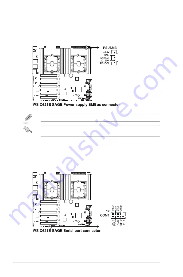
18. Serial port connector (10-1 pin COM1)
This connector is for a serial (COM) port. Connect the serial port module cable to this
connector, then install the module to a slot opening at the back of the system chassis.
17. Power Supply SMBus connector (5-pin PSUSMB)
This connector allows you to connect SMBus (System Management Bus) to the PSU
(power supply unit) to read PSU information. Devices communicate with an SMBus
host and/or other SMBus devices using the SMBus interface.
This connector functions only when you enable the ASUS ASMB card.
Power supply is required to meet PMBus specification and customized BMC FW may be
needed. Please contact ASUS if your need further support
Summary of Contents for E900 G4
Page 1: ...Workstation E900 G4 User Guide ...
Page 60: ...Chapter 2 Hardware Setup 2 40 ...
Page 88: ...Chapter 3 Motherboard Information 3 28 ...
Page 110: ...4 22 Chapter 4 BIOS Setup ...
Page 134: ...5 24 Chapter 5 RAID Configuration ...
Page 135: ...A Appendix Appendix ...