


24
of
54
TECHNICIANS' manual
Core200
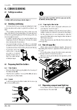
5.6
Drilling the support base
If holes need to be drilled into the support base to
let the water inlet hoses, outlet hoses and power cables
pass through, follow the directions given in the draw-
ings below.
5.7
Hydraulic connection
5.7.1 Water supply
The appliance’s water supply must provide water
which is suitable for human consumption, and must
conform with the regulations in force in the place of
installation. The owner/ manager of the system must
give confirmation to the installer that the water meets
the above requirements:
5.7.2 Materials to be used
During the installation of the appliance, only the
components and materials supplied with the appliance
are to be used. Should the use of other components be
necessary, the installer must verify their suitability to be
used in contact with drinking water.
5.7.3 Hydraulic connections
The installer must carry out the hydraulic connections
in accordance with the hygiene norms and the hydraulic
safety norms for environmental protection in force in the
place of installation.
1. Add a tap to the water supply so as to stop water
from flowing to the machine;
2. In order to prevent damage, it is advisable to install
the water purification filter where it will be pro-
tected from accidental blows;
3. If there is no water purification filter and/or motor
pump, connect the water mains
(11)
directly to the
machine's water inlet
(5)
;
4. When connecting the machine's tray
(4)
to the
sewer drain
(10)
, avoid overly tight curves or kinks,
and make sure that there is sufficient inclination for
water to flow to the drain;
5. The drain must be connected to a siphon that can
be inspected and periodically cleaned, in order to
prevent unpleasant odours;
6. To avoid oxidisation building up and damage to the
machine over time, do not use iron connections for
the hydraulic system, even if they are galvanised.
After installation and before using the machine, the water in the
hydraulic circuits must be replaced, as indicated in par. 6.10.
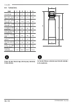
COMPATTA
400 mm
250 mm
Front machine
100 mm
320 mm
100 mm
2 GROUPS
350 mm
580 mm
Front machine
320 mm
100 mm
100 mm
3 GROUPS
590 mm
820 mm
Front machine
320 mm
100 mm
100 mm
Summary of Contents for 10003318
Page 53: ......


