


B A G O
REMOVE THESE
PARTS FOR:
Step 5
s t e p 5
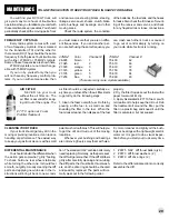
CLUTCH ASSEMBLY
Install your #7601 clutch shoes on the clutch
pins on the flywheel as shown.
Install one #6902 flanged bearing followed by
the #7605 15 tooth clutch bell and the second
#6902 flanged bearing.
Install the #2661 clutch nut E-clip where shown.
Continue to Step 7.
4
6902, qty 2
3/16 x 5/16 bearing
flanged
1:1
22
7601
6902
7605
2661
6902
2661, qty 1
clutch nut E-clip
1:1
7601, qty 2
clutch shoe
7605, qty 2
clutch bell
15 tooth
B A G O
REMOVE THESE
PARTS FOR:
Step 6
T O O L S U S E D
6902, qty 2
3/16 x 5/16 bearing
flanged
1:1
2661, qty 1
clutch nut E-clip
1:1
7601, qty 2
clutch shoe
7605, qty 2
clutch bell
15 tooth
B A G O
REMOVE THESE
PARTS FOR:
Step 4
T O O L S U S E D
5/16"
s t e p 4
FLYWHEEL ASSEMBLY
Install two #7618 collet spacers followed by one
#7618 collet.
Install the #7610 or #7612 flywheel followed by
the #7602 special clutch nut. Tighten the clutch
nut securely down, locking the flywheel to the
collet. Get it as tight as you can.
Continue to Step 5 for Clutch Assembly.
3
7602, qty 1
clutch nut
(Dynamite engine)
7618 spacer
7618 collet
flywheel
7610 (non pull start)
7612 (pull start)
7602
5/16"
7618, qty 2
spacer
7618, qty 1
collet
1:1
1:1
7618, qty 1
spacer
7618, qty 1
collet
1:1
1:1
The clutch shoes should
be facing this direction
when installed.
flywheel, qty 1
7610 (non pull start)
OR 7612 (pull start)
OR
flywheel, qty 1
7610 (non pull start)
OR 7612 (pull start)
OR
D Y N A M I T E E N G I N E S o n l y


