


Gate Controller ATC 100
14
6. Program settings
In this description of the settings a maximum
configuration of the system is presupposed. If a
component is missing in the system the appropriate
subfunction of the controller is inactive (poss. insert
bridge).
The display of the ATC100 control module is implemented
as a two-line display. The upper line generally indicates
the mode of operation. The second line indicates the
selected function depending upon the mode of operation.
In the mode automatic the conditions of the gate system
are displayed here.
6.3 ADJUST
To change the ATC 100 settings the button
MENU
SELECT
and the button
FUNCTION
have to be pressed
at the same time (approx. 2 sec.) to reach the adjust-
menu.
The parameter to be changed can be selected by pressing
the button
FUNCTION
(the individual parameters are
indicated "rolling wise"). The appropriate selected
parameter can be adjusted by pressing the button
OPEN(+)
or
CLOSE(-)
.
If all parameters are adjusted in this way, press the buttons
MENU SELECT
and
FUNCTION
to leave the adjust-
menu. If no button is actuated in the adjust-mode for 90
sec., all adjusted parameters will be saved and the
controller switches to the
MANUAL MODE
.
With the switch
MENU SELECT
the mode "AUTOMATIC"
can be selected again.
The parameters appear in the following sequence and
have the functions as described.
•
LCD
Deutsch / English / Francais Pre-setting: Deutsch
Language setting for control module.
•
Run Time
1 up to 240 sec.
Pre-setting: 120 sec.
In order to protect drive and gate mechanics the run time is
monitored during the opening- and closing phase. If the
appropriate limit switch is not reached in the programmed
time the controller stops. If this happens the control module
displays ERROR run time. The adjusted run time should be
selected 10 sec. longer than the maximum gate run time.
•
OPEN TIME
0 up to 600 sec.
Pre-setting: 0 sec.
The counting of time begins after reaching the limit-switch
OPEN. After expiring this time the advance warning time
begins followed by the automatic closing of the gate.
The automatic closing is deactivated if the opening time is
adjusted to 0.
Automatic closing can also be prevented on the
hardware side. For this the Jumper 1 is to be
removed.
•
PRE-WARN.
(Pre-Warning)
0 up to 120 sec.
Pre-setting: 0 sec.
(Applicable only in closing-movement)
With setting 0 the gate starts immediately after a moving
instruction. With adjusted time the pre-warning is started
and the gate only starts to run after expiration of the adjusted
time.
With the button
MENU SELECT
4 modes of operation
can be adjusted. By actuating the button (approx. 2 sec.)
the individual modes of operation can be selected in
sequence.
AUTOMATIK
TOTMANNBETRIEB
EINGABE
DIAGNOSE
In the different modes of operation the buttons
CLOSE(-)
and
OPEN(+
) have different functions.
6.1 AUTOMATIC
The button
CLOSE(-)
and
OPEN(+
) have no function.
6.2 MANUAL MODE
In the manual mode the drive can be opened with the
button
OPEN (+)
and be closed with the button
CLOSE(-)
. (with faulty or missing safety devices no
manual mode operation is possible).
9
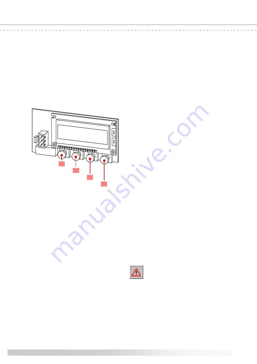
Menu select
button
function
button
open (+)
button
close (-)
button
10
11
8
Summary of Contents for 302030
Page 19: ...19 ...


