Doc ID : ADR111A_IM_01
Ref ID : ADR111A/IM/FC
Rev No. : 04
Page No. : 107 of 127
ADR111A /
ADR211A
9
FLOW CHART OVERVIEW
9.1
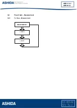
Main Menu
After the Power ON or when LED RESET + HW RESET keys are pressed the following windows
will be displayed and the user can scroll the main menu as given below
ADR211A V–02.00
Unit ID = 001
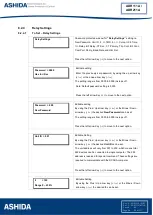
MEASUREMENT
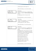
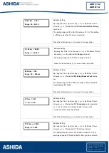
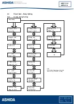
Relay Settings
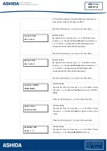
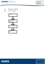
Trip Test
Fault 1
Fault 2
Fault 3
Fault 4
Error Log
Status
DATE / TIME
Ashida Digital
Relay
Fault 5
I = 0000A
6
i = 000.00
6
3
4
3
4
3
4
3
4
3
4
3
4
3
4
3
4
3
4
3
4
3
4
Summary of Contents for ADR111A
Page 10: ...Page intentionally Left Blank...
Page 16: ...Page intentionally Left Blank...
Page 27: ...Page intentionally Left Blank...
Page 42: ...Page intentionally Left Blank...
Page 52: ...Page intentionally Left Blank...
Page 64: ...Page intentionally Left Blank...
Page 68: ...Page intentionally Left Blank...
Page 73: ...Page intentionally Left Blank...
Page 84: ...Page intentionally Left Blank...
Page 104: ...Page intentionally Left Blank...
Page 115: ...Page intentionally Left Blank...
Page 119: ...Doc ID ADR111A_IM_01 Ref ID ADR111A IM DR Rev No 04 Page No 119 of 127 ADR111A ADR211A...
Page 120: ...Page intentionally Left Blank...
Page 128: ......

