Chapter 3 Installing the switch
41
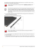
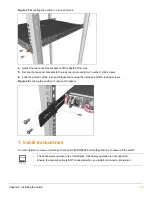
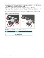
Figure 25:
Connecting a power cord to the switch
3.
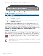
Check the LEDs. See
“Chassis LEDs on the front of the switch” on page 13
.
9. Connect a management console
The Aruba 8325 switch has a full-featured, easy to use console interface for performing switch management tasks,
including the following:
•
Enabling switch ports (ports are disabled by default).
•
Monitoring switch and port status and observing network activity statistics.
•
Modifying the switch’s configuration to optimize switch performance, enhancing network traffic control, and
improving network security.
•
Reading the event log and accessing diagnostic tools to help in troubleshooting.
•
Downloading new software to the switch.
•
Adding passwords to control access to the switch from the console, Web browser interface, and network
management stations.
The console can be accessed through these methods:
•
Out-of-band serial:
Use a serial cable (not included) for connecting a workstation running suitable VT-100
terminal emulation software directly to the switch’s RJ-45 Console Port. A DB9-to-RJ-45 console cable can be
ordered from HPE: JL448A, Aruba X2C2 RJ45 to DB9 Console Cable.
•
Out-of-band network:
Access the console using SSH from a PC or UNIX station on the network running
suitable VT-100 terminal emulation software.
The switch can simultaneously support one console session through the Console Port and multiple network
SSH sessions.
Terminal configuration
To connect a console to the switch, configure the PC terminal emulator as a DEC VT-100 (ANSI) terminal or use a
VT-100 terminal, and configure either one to operate with these settings:
•
A baud rate of 115200.
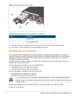
One power supply provides power to operate the switch. Installing a second power supply can
provide power to the switch in case the initial power supply fails. If the power supplies are plugged
into different AC power sources, redundant power can be supplied in case of loss of one of the AC
power sources.

