8
Aruba 8325 Switch Installation and Getting Started Guide
◦
Console port
◦
Out-of-band management (OOBM)
◦
LEDs
◦
Reset button
•
Back of the switch:
◦
Power supplies and connectors
◦
Fan assemblies
◦
LED indicators for fan assemblies and power supplies
•
Switch features
◦
Hardware features
◦
Software features
◦
Management software
Front of the switch
8325-48Y8C JL624A and JL625A switches
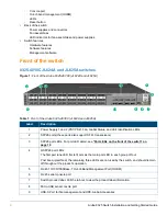
Figure 1:
Front of the Aruba 8325-48Y8C (JL624A and JL625A)
Table 1:
Front of the Aruba 8325-48Y8C (JL624A and JL625A)
Label
Description
1
Power Supply 1 and 2 (PS1/PS2), Fan, Global Status, and Unit Identification LEDs
2
SFP28 ports (these ports also support SFP+ transceivers)
3
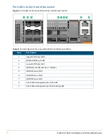
SFP28 port LEDs. For port LED detail, see
“Port LEDs on the front of the switch” on
page 16
.
4
QSFP28 port LEDs
The first port lane LED (far left) acts as the main port LED in each group of four.
Post boot-up/self-test, the remaining three LEDs are not used by the switch, and should remain
off throughout the product's operation.
5
RJ-45 10/100/1000Base-T Out-of-Band Management Port (OOBM)
6
RJ-45 serial console port
7
Switch product label. Pull the tab out to view the product label information.
8
Micro-USB serial console port
9
USB-A Port for file management and HPE-Aruba Accessories
2
3
5
8
6
11
4
9
7
1
10


