


Chapter 2 Introducing the Aruba 8325 Switch
21
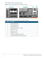
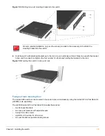
Figure 10:
Back of the Aruba 8325-32C (JL626A and JL627A)
5
Fan assembly 3
6
Fan assembly 2
7
Fan assembly 1
8
Power supply status LED
9
Power supply 1
10
Ground lug
11
Fan assembly status LED
12
Color-coded power supply release latch
red = front-to-back air flow
blue = back-to-front air flow
13
Ground lug
Table 15:
Back of the Aruba 8325-32C (JL626A and JL627A) labels and descriptions
Label
Description
1
Power supply 2
1
2
Fan assembly 6
3
Fan assembly 5
4
Fan assembly 4
5
Fan assembly status LED
6
Fan assembly 3
7
Fan assembly 2
8
Fan assembly 1
9
Power supply status LED
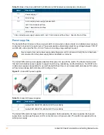
Table 14:
Back of the Aruba 8325-48Y8C (JL624A and JL625A) switch labels and descriptions (Continued)
Label
Description
4
1
8
7
6
9
3
2
5
10
12
11
13