PERFORMANCE
Copyright 2001
4-2
DAC128V HARDWARE REFERENCE
4.3 IP Module Accesses
There are some parameters that are important when evaluating an IP Module’s
performance on a specific carrier board. These involve the assertion and negation, or
driving to logic state versus high impedance states, of signals from the IP Module to the
carrier, with reference to the rising edge of ICLK. According to specification, these state
changes must occur within 40 ns. Figure 4-2 presents just one of the logic state analysis
figures captured for the development of the data in Table 4-1. Table 4-2 depicts an I/O
write to the first I/O location (IPA = 0x00) of data whose least significant nibble is zero
(IPD[3:0] = 0). The important parameter here is that it typically takes 10 ns to negate
N_ACK.
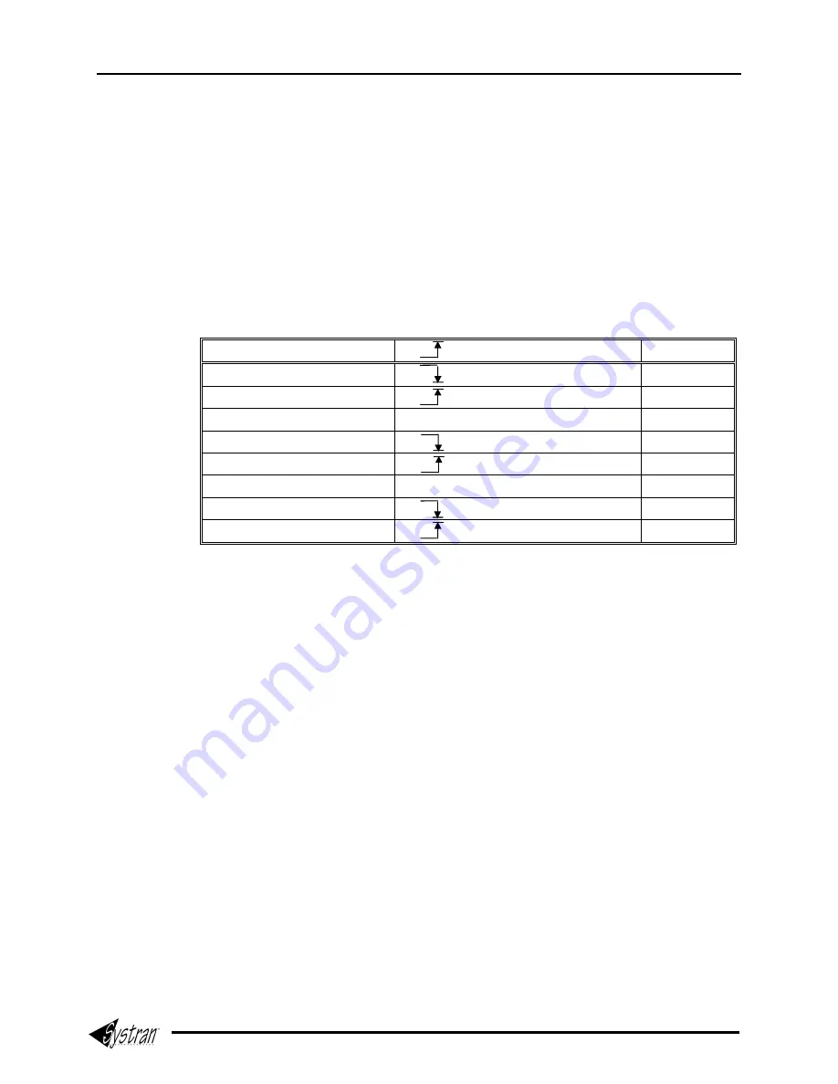
Table 4-1 IP Module Access Time
Function/Operation ICLK
Until Time
I/O READ @ IPA = 0x00
N_ACK
10 ns
I/O READ @ IPA = 0x00
N_ACK
11 ns
I/O READ @ IPA = 0x00
IPDbus’ HIGH to LOW impedance
22 ns
I/O WRITE @ IPA = 0x00
N_ACK
09 ns
I/O WRITE @ IPA = 0x00
N_ACK
10 ns
ID READ @ IPA = 0x00
IPDbus’ HIGH to LOW impedance
06 ns
ID READ @ IPA = 0x00
N_ACK
10 ns
ID READ @ IPA = 0x00
N_ACK
11 ns
There is one additional note to add concerning DAC128V IP Module operations.
Normally, an IP Module does not drive the IPDbus to a low impedance state until (and
during) its assertion of N_ACK during HOLD and termination cycles. To date, this policy
has been faithfully followed in the design of all Systran’s IP Modules. The best practical
reason for this is to avoid data bus contention with a carrier or other IP Module that is
slow to release the IPDbus following a preceding transfer without an idle cycle. The
specification requires the release within 40 ns. There is no restriction against an IP
Module driving the IPDbus during the select cycle.
The DAC’s read-back registers have a very long data valid delay time, potentially
approaching 160 ns following the assertion of their appropriate chip-select signal. For
this reason, the IPDbus is coupled to the DAC’s read buffers as soon as possible in the
read transfer to provide the maximum amount of time for data line stabilization and
carrier data setup time for capturing the data in the rising edge of the ICLK signal at the
termination of the transfer. This phenomenon is depicted in Figure 4-2, and Figure 4-3.
Figure 4-3 also shows why READ gates were installed, as described in Chapter 2,
PRODUCT OVERVIEW.
Artisan Technology Group - Quality Instrumentation ... Guaranteed | (888) 88-SOURCE | www.artisantg.com
Summary of Contents for DAC128V
Page 3: ...Artisan Technology Group Quality Instrumentation Guaranteed 888 88 SOURCE www artisantg com ...
Page 37: ...Artisan Technology Group Quality Instrumentation Guaranteed 888 88 SOURCE www artisantg com ...
Page 41: ...Artisan Technology Group Quality Instrumentation Guaranteed 888 88 SOURCE www artisantg com ...
Page 47: ...Artisan Technology Group Quality Instrumentation Guaranteed 888 88 SOURCE www artisantg com ...
Page 55: ...Artisan Technology Group Quality Instrumentation Guaranteed 888 88 SOURCE www artisantg com ...
Page 59: ...Artisan Technology Group Quality Instrumentation Guaranteed 888 88 SOURCE www artisantg com ...


