Controls, Indicators, and Connectors
SharpSwitch™ PCIE-9205 Installation and Use (6806800U18D)
53
53
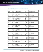
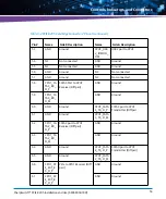
GND
Ground
CPU1_USB
2_IOMOD_
DM
USB2 port to CPU1
54
NC
Not connected
GND
Ground
55
NC
Not connected
GND
Ground
56
GND
Ground
NC
Not connected
57
GND
Ground
NC
Not connected
58
CPU1_SA
TA3_RX_
D_P
SATA3 Port to CPU1
Receiver (Diff pair)
GND
Ground
59
CPU1_SA
TA3_RX_
D_M
GND
Ground
60
GND
Ground
CPU1_SATA
3_TX_D_P
SATA3 port to CPU1
Transmitter (Diff pair
61
GND
Ground
CPU1_SATA
3_TX_D_M
62
CPU1_SA
TA2_RX_
D_P
SATA2 port to CPU1
Receiver (Diff pair)
GND
Ground
63
CPU1_SA
TA2_RX_
D_M
GND
Ground
64
GND
Ground
CPU1_SATA
2_TX_D_P
SATA0 port to CPU1
Transmitter (Diff pair)
65
GND
Ground
CPU1_SATA
2_TX_D_M
66
CPU1_P2
E_EXT_R
X_D_P
PCIe to CPU1 Receiver (Diff
pair)
GND
Ground
67
CPU1_P2
E_EXT_R
X_D_P
GND
Ground
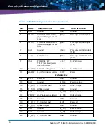
Table 3-2 PCIE-9205 Card Edge Connector 2 Pinout (continued)
Pin #
Name
Side B Description
Name
Side A Description
Summary of Contents for SharpSwitch PCIE-9205
Page 1: ...SharpSwitch PCIE 9205 Installation and Use P N 6806800U18D March 2018 ...
Page 6: ...SharpSwitch PCIE 9205 Installation and Use 6806800U18D 6 Contents ...
Page 8: ...SharpSwitch PCIE 9205 Installation and Use 6806800U18D 8 List of Tables ...
Page 10: ...SharpSwitch PCIE 9205 Installation and Use 6806800U18D 10 List of Figures ...
Page 22: ...SharpSwitch PCIE 9205 Installation and Use 6806800U18D Safety Notes 22 ...
Page 30: ...SharpSwitch PCIE 9205 Installation and Use 6806800U18D Sicherheitshinweise 30 ...
Page 62: ...Controls Indicators and Connectors SharpSwitch PCIE 9205 Installation and Use 6806800U18D 62 ...
Page 68: ...Functional Description SharpSwitch PCIE 9205 Installation and Use 6806800U18D 68 ...
Page 86: ...BIOS SharpSwitch PCIE 9205 Installation and Use 6806800U18D 86 ...
Page 101: ......

