Chapter 3
SharpSwitch™ PCIE-9205 Installation and Use (6806800U18D)
45
Controls, Indicators, and Connectors
This chapter contains information about the connectors, indicators, and controls associated
with the PCIE-9205 card. The following figure shows the faceplate view of PCIE-9205 card.
3.1
Connectors
The PCIE-9205 card comes with two gold finger edge connectors.
3.1.1
Edge Connector 1
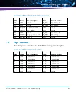
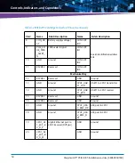
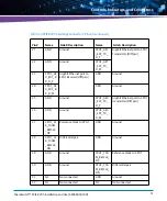
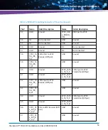
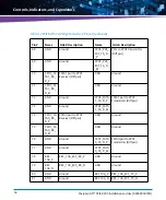
This section provides information about the PCIE-9205 card edge connector 1 pinout.
Figure 3-1
Faceplate
User LED
COM0
Via USB
USB
P0
100G Ethernet
QSFP28
P1
100G Ethernet
QSFP28
Reset
Button
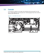
Dual in-line Package (DIP) switches (SW100, SW101, SW200) on the back of the board are
for debug purpose only. Their default settings are off.
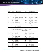
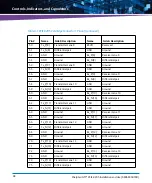
Table 3-1 PCIE-9205 Card Edge Connector 1 Pinout
Pin #
Name
Side B Description
Name
Side A Description
1
+12V
+12 Volt power
PRSNT#1
PCIe edge present input
2
+12V
+12 Volt power
+12V
+12 Volt power
3
+12V
+12 Volt power
+12V
+12 Volt power
Summary of Contents for SharpSwitch PCIE-9205
Page 1: ...SharpSwitch PCIE 9205 Installation and Use P N 6806800U18D March 2018 ...
Page 6: ...SharpSwitch PCIE 9205 Installation and Use 6806800U18D 6 Contents ...
Page 8: ...SharpSwitch PCIE 9205 Installation and Use 6806800U18D 8 List of Tables ...
Page 10: ...SharpSwitch PCIE 9205 Installation and Use 6806800U18D 10 List of Figures ...
Page 22: ...SharpSwitch PCIE 9205 Installation and Use 6806800U18D Safety Notes 22 ...
Page 30: ...SharpSwitch PCIE 9205 Installation and Use 6806800U18D Sicherheitshinweise 30 ...
Page 62: ...Controls Indicators and Connectors SharpSwitch PCIE 9205 Installation and Use 6806800U18D 62 ...
Page 68: ...Functional Description SharpSwitch PCIE 9205 Installation and Use 6806800U18D 68 ...
Page 86: ...BIOS SharpSwitch PCIE 9205 Installation and Use 6806800U18D 86 ...
Page 101: ......


