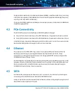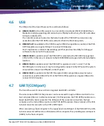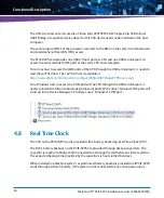
Controls, Indicators, and Connectors
SharpSwitch™ PCIE-9205 Installation and Use (6806800U18D
)
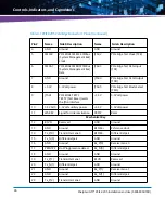
52
33
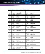
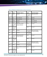
NC
Not connected
NC
Not connected
34
NC
Not connected
NC
Not connected
35
NC
Not connected
NC
Not connected
36
NC
Not connected
NC
Not connected
37
CLK_OU
T_P
SYNCE CLK P
CLK_IN_P
SYNCE CLK P
38
CLK_OU
T_N
SYNCE CLK M
CLK_IN_N
SYNCE CLK M
39
GND
Ground
GND
Ground
40
NC
Not connected
NC
Not connected
41
NC
Not connected
NC
Not connected
42
NC
Not connected
NC
Not connected
43
NC
Not connected
GND
Ground
44
GND
Ground
NC
Not connected
45
CPU1_LP
C_LAD0
LPC Port to CPU1 bus
GND
Ground
46
CPU1_LP
C_LAD1
CPU1_LPC_
LFRAME_N
LPC Frame to CPU1
47
CPU1_LP
C_LAD2
CPU1_SERI
RQ
LPC Interrupt signal
48
CPU1_LP
C_LAD3
PCH_SKL1_
PLTRST_N
LPC reset signal
49
GND
Ground
GND
Ground
50
NC
Not connected
CPU1_CLK
OUT_LPC0
LPC clock to CPU1
51
NC
Not connected
GND
Ground
52
GND
Ground
CPU1_USB
2_IOMOD_
DP
USB2 port to CPU1
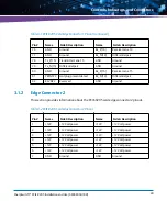
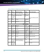
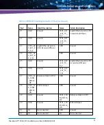
Table 3-2 PCIE-9205 Card Edge Connector 2 Pinout (continued)
Pin #
Name
Side B Description
Name
Side A Description
Summary of Contents for SharpSwitch PCIE-9205
Page 1: ...SharpSwitch PCIE 9205 Installation and Use P N 6806800U18D March 2018 ...
Page 6: ...SharpSwitch PCIE 9205 Installation and Use 6806800U18D 6 Contents ...
Page 8: ...SharpSwitch PCIE 9205 Installation and Use 6806800U18D 8 List of Tables ...
Page 10: ...SharpSwitch PCIE 9205 Installation and Use 6806800U18D 10 List of Figures ...
Page 22: ...SharpSwitch PCIE 9205 Installation and Use 6806800U18D Safety Notes 22 ...
Page 30: ...SharpSwitch PCIE 9205 Installation and Use 6806800U18D Sicherheitshinweise 30 ...
Page 62: ...Controls Indicators and Connectors SharpSwitch PCIE 9205 Installation and Use 6806800U18D 62 ...
Page 68: ...Functional Description SharpSwitch PCIE 9205 Installation and Use 6806800U18D 68 ...
Page 86: ...BIOS SharpSwitch PCIE 9205 Installation and Use 6806800U18D 86 ...
Page 101: ......


