Controls, Indicators, and Connectors
SharpSwitch™ PCIE-9205 Installation and Use (6806800U18D
)
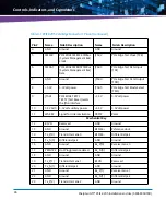
50
8
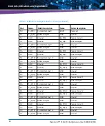
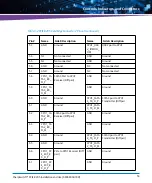
CON_VB
AT
Battery supply voltage[
CON SLOT
ID0
Board identification address
bits
9
PCIE_ED
GE_SMB
_ALERT_
N
SM Bus alert signal
CON SLOT
ID1
10
GND
Ground
CON SLOT
ID2
11
RSVD#2
Reserved
CON SLOT
ID3
Mechanical Key
12
RSVD#2
Reserved
GND
Ground
13
GND
Ground
CPU1_UAR
T1_TXD
UART1 to CPU1 transmitter
14
GND
Ground
CPU1_UAR
T1_RXD
UART1 to CPU1 receiver
15
RSVD#2
Reserved
GND
Ground
16
RSVD#2
Reserved
GND
Ground
17
GND
Ground
CPU1_USB
2_BMC_DP
USB port to CPU1
18
GND
Ground
CPU1_USB
2_BMC_D
M
USB port to CPU1
19
CPU1_GE
1_EXT_R
X_D_P
Gigabit Ethernet port to
CPU1 Receiver (Diff pair)
GND
Ground
20
CPU1_GE
1_EXT_R
X_D_M
GND
Ground
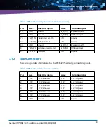
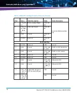
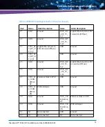
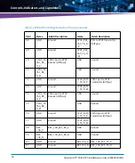
Table 3-2 PCIE-9205 Card Edge Connector 2 Pinout (continued)
Pin #
Name
Side B Description
Name
Side A Description
Summary of Contents for SharpSwitch PCIE-9205
Page 1: ...SharpSwitch PCIE 9205 Installation and Use P N 6806800U18D March 2018 ...
Page 6: ...SharpSwitch PCIE 9205 Installation and Use 6806800U18D 6 Contents ...
Page 8: ...SharpSwitch PCIE 9205 Installation and Use 6806800U18D 8 List of Tables ...
Page 10: ...SharpSwitch PCIE 9205 Installation and Use 6806800U18D 10 List of Figures ...
Page 22: ...SharpSwitch PCIE 9205 Installation and Use 6806800U18D Safety Notes 22 ...
Page 30: ...SharpSwitch PCIE 9205 Installation and Use 6806800U18D Sicherheitshinweise 30 ...
Page 62: ...Controls Indicators and Connectors SharpSwitch PCIE 9205 Installation and Use 6806800U18D 62 ...
Page 68: ...Functional Description SharpSwitch PCIE 9205 Installation and Use 6806800U18D 68 ...
Page 86: ...BIOS SharpSwitch PCIE 9205 Installation and Use 6806800U18D 86 ...
Page 101: ......


