200
Options List
Configure Network Settings
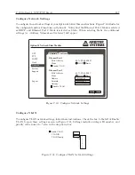
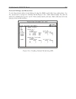
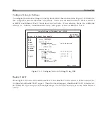
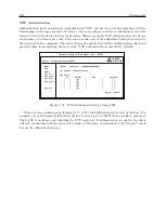
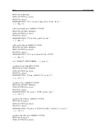
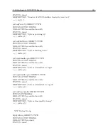
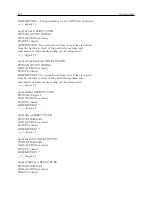
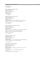
To configure the network settings of your Option 34 follow these instructions. Figure C.45 illustrates
the configurable network functions on Option 34. Notice that the Ethernet Port 1 Mode is selected
as DHCP and Ethernet Port 2 Mode is selected as Static. When selecting Static, the additional
settings (i.e. Address, Netmask and Gateway) will appear as seen on Ethernet Port 2.
Status [Configure]
Ethernet Port 1
Hardware Address 64:73:E2:00:17:38
(*) DHCP ( ) Static
[ ] Enable VLAN
Ethernet Port 2
Hardware Address 64:73:E2:00:17:39
( ) DHCP (*) Static
IP Address [10.10.1.185 ]
Netmask [255.255.0.0 ]
Gateway [ ]
[X] Enable VLAN
VLAN ID [123 ]
VLAN Priority [2]
Apply Reset
ARBITER
SYSTEMS
Option 34 Network Time Module
NTP
PTP
SNMP
Clock
[Network]
System
Support
Logout
Computer Name (or IP address) – ssh – 80x24
Figure C.45: Configure Network Settings Using SSH
Enable VLAN
From Figure C.45 notice that on Ethernet Port 2 that Enable VLAN is selected. When selected, the
two lines below Enable VLAN appear. These two lines disappear when Enable VLAN is deselected.
For VLAN ID, type in up to any four-digit integer. For VLAN Priority, type in any value between
0 and 7.
Summary of Contents for 1084A
Page 4: ...iv ...
Page 6: ...vi ...
Page 18: ...xviii LIST OF FIGURES ...
Page 24: ...4 Unpacking the Clock ...
Page 36: ...16 Connecting Inlet Power Input and Output Signals ...
Page 44: ...24 GPS Antenna and Cable Information ...
Page 114: ...94 Startup and Basic Operation ...
Page 123: ...B 4 Physical Dimensions 103 Figure B 1 Suggested Mounting of the AS0094500 Surge Arrester ...
Page 124: ...104 Using Surge Arresters ...
Page 134: ...114 Options List C 6 2 Option 06 Firmware Setup Figure C 3 Option 06 Firmware Setup ...
Page 142: ...122 Options List Figure C 5 Option 06 Output Jumper Settings ...
Page 158: ...138 Options List Figure C 13 Option 17 Board Layout and Jumper Locations ...
Page 163: ...C 13 Option 20A Four Fiber Optic Outputs 143 Figure C 14 Option 20A Jumper Locations ...
Page 170: ...150 Options List Figure C 16 Option 23 Internal Jumper Setup ...
Page 172: ...152 Options List Figure C 17 Option 27 Jumper Locations ...
Page 190: ...170 Options List Figure C 20 Option 29 Connector Signal Locations ...
Page 246: ...226 Options List ...

