208
Options List
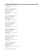
12.
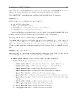
PTP Application Stops
– notifies when PTP service stops.
13.
SNMP Application Start
– notifies when SNMP service starts.
14.
SNMP Application Stop
– notifies when SNMP service stops.
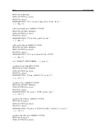
•
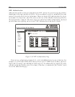
Trap Receivers
– Select this item to enable SNMP to send messages to snmp receivers.
1.
IP Address 1
– Type in the IP address of snmp receiver number 1.
2.
IP Address 2
– Type in the IP address of snmp receiver number 2.
3.
IP Address 3
– Type in the IP address of snmp receiver number 3.
MIB Table
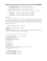
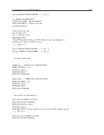
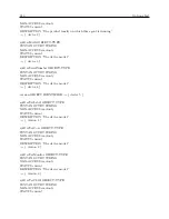
The text of the MIB table, listed below, is current as of the publication date of this manual, and
is produced by Arbiter’s technical team. Updates are available by download from the Arbiter web
site. Also, the SNMP agent that runs on Option 34 is also available for download and use in the
Model 1084A/B/C. The MIB table is normally loaded in a MIB browser and the agent is normally
uploaded into the Option 34.
–
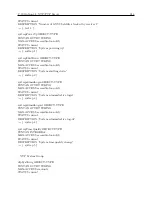
– ARBITER ALL MIB, Revision 0.0003, 3 DEC 2012
–
ARBITER-ALL-MIB DEFINITIONS ::= BEGIN
IMPORTS
MODULE-IDENTITY, OBJECT-TYPE, enterprises, Integer32, Unsigned32 FROM SNMPv2-SMI
TEXTUAL-CONVENTION, TruthValue FROM SNMPv2-TC
;
–
– The position within the OID hierarchy of this MIB:
–
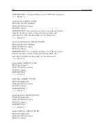
arbiter OBJECT IDENTIFIER ::=
{
enterprises 39849
}
sys MODULE-IDENTITY
LAST-UPDATED “201205250000Z”
ORGANIZATION “Arbiter Systems”
CONTACT-INFO
“
Arbiter Systems, Inc.
Paso Robles, CA
Tel: +1 805 237 3831”
DESCRIPTION
“This MIB module defines a MIB which provides general information
about an Arbiter Systems’ product.”
::=
{
arbiter 1
}
device OBJECT IDENTIFIER ::=
{
sys 1
}
diag OBJECT IDENTIFIER ::=
{
sys 2
}
config OBJECT IDENTIFIER ::=
{
sys 3
}
gnss OBJECT IDENTIFIER ::=
{
sys 4
}
Summary of Contents for 1084A
Page 4: ...iv ...
Page 6: ...vi ...
Page 18: ...xviii LIST OF FIGURES ...
Page 24: ...4 Unpacking the Clock ...
Page 36: ...16 Connecting Inlet Power Input and Output Signals ...
Page 44: ...24 GPS Antenna and Cable Information ...
Page 114: ...94 Startup and Basic Operation ...
Page 123: ...B 4 Physical Dimensions 103 Figure B 1 Suggested Mounting of the AS0094500 Surge Arrester ...
Page 124: ...104 Using Surge Arresters ...
Page 134: ...114 Options List C 6 2 Option 06 Firmware Setup Figure C 3 Option 06 Firmware Setup ...
Page 142: ...122 Options List Figure C 5 Option 06 Output Jumper Settings ...
Page 158: ...138 Options List Figure C 13 Option 17 Board Layout and Jumper Locations ...
Page 163: ...C 13 Option 20A Four Fiber Optic Outputs 143 Figure C 14 Option 20A Jumper Locations ...
Page 170: ...150 Options List Figure C 16 Option 23 Internal Jumper Setup ...
Page 172: ...152 Options List Figure C 17 Option 27 Jumper Locations ...
Page 190: ...170 Options List Figure C 20 Option 29 Connector Signal Locations ...
Page 246: ...226 Options List ...

