C.19 Option 34: NTP/PTP Server
189
Configure SNMP
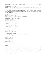
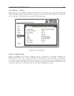
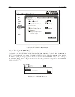
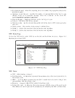
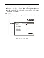
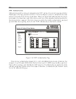
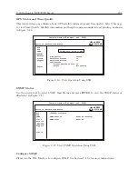
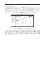
Follow these instructions to configure SNMP operation in the Option 34. Figure C.34 illustrates
the different selections for enabling the service and selecting traps (notifications). For definitions
of SNMP “Configure” selections, see Section C.19.4.
Option 34 Network Time Module
Status
Configure
NTP
PTP
Clock
Network
System
Support
Logout
SNMP
Enable SNMP Service
Enable SNMP Traps
System Start
System Stop
Admin Login
Admin Logout
System Time Quality
System Time Set
System Time Change
Zero Satellites Visible
NTP Application Start
NTP Application Stop
PTP Application Start
PTP Application Stop
SNMP Application Start
SNMP Application Stop
Trap Receivers
IP Address 1
IP Address 2
IP Address 3
10.10.1.236
Apply
Reset
Figure C.34: SNMP Configuration Page
Checking the box enables the specific item; unchecking disables the specific item in the SNMP
Configure page. For example, checking the “Enable SNMP Service” turns ON the service. Enabling
SNMP Traps and checking specific SNMP traps (or notifications) will not send any notification
unless a Trap Receiver is specified by an IP address. Make sure to click the Apply button or the
changes will be lost.
Summary of Contents for 1084A
Page 4: ...iv ...
Page 6: ...vi ...
Page 18: ...xviii LIST OF FIGURES ...
Page 24: ...4 Unpacking the Clock ...
Page 36: ...16 Connecting Inlet Power Input and Output Signals ...
Page 44: ...24 GPS Antenna and Cable Information ...
Page 114: ...94 Startup and Basic Operation ...
Page 123: ...B 4 Physical Dimensions 103 Figure B 1 Suggested Mounting of the AS0094500 Surge Arrester ...
Page 124: ...104 Using Surge Arresters ...
Page 134: ...114 Options List C 6 2 Option 06 Firmware Setup Figure C 3 Option 06 Firmware Setup ...
Page 142: ...122 Options List Figure C 5 Option 06 Output Jumper Settings ...
Page 158: ...138 Options List Figure C 13 Option 17 Board Layout and Jumper Locations ...
Page 163: ...C 13 Option 20A Four Fiber Optic Outputs 143 Figure C 14 Option 20A Jumper Locations ...
Page 170: ...150 Options List Figure C 16 Option 23 Internal Jumper Setup ...
Page 172: ...152 Options List Figure C 17 Option 27 Jumper Locations ...
Page 190: ...170 Options List Figure C 20 Option 29 Connector Signal Locations ...
Page 246: ...226 Options List ...

