000-015-480 Issue 5
22
nd
May 2017
Anite S-CORE Getting Started Guide
Page 15 of 47
Commercial In Confidence
4.
Select Obtain an IP address automatically.
5.
Click
OK
to confirm the changes.
3.1.2
WLAN Test Accelerator Setup
Cabling Instructions
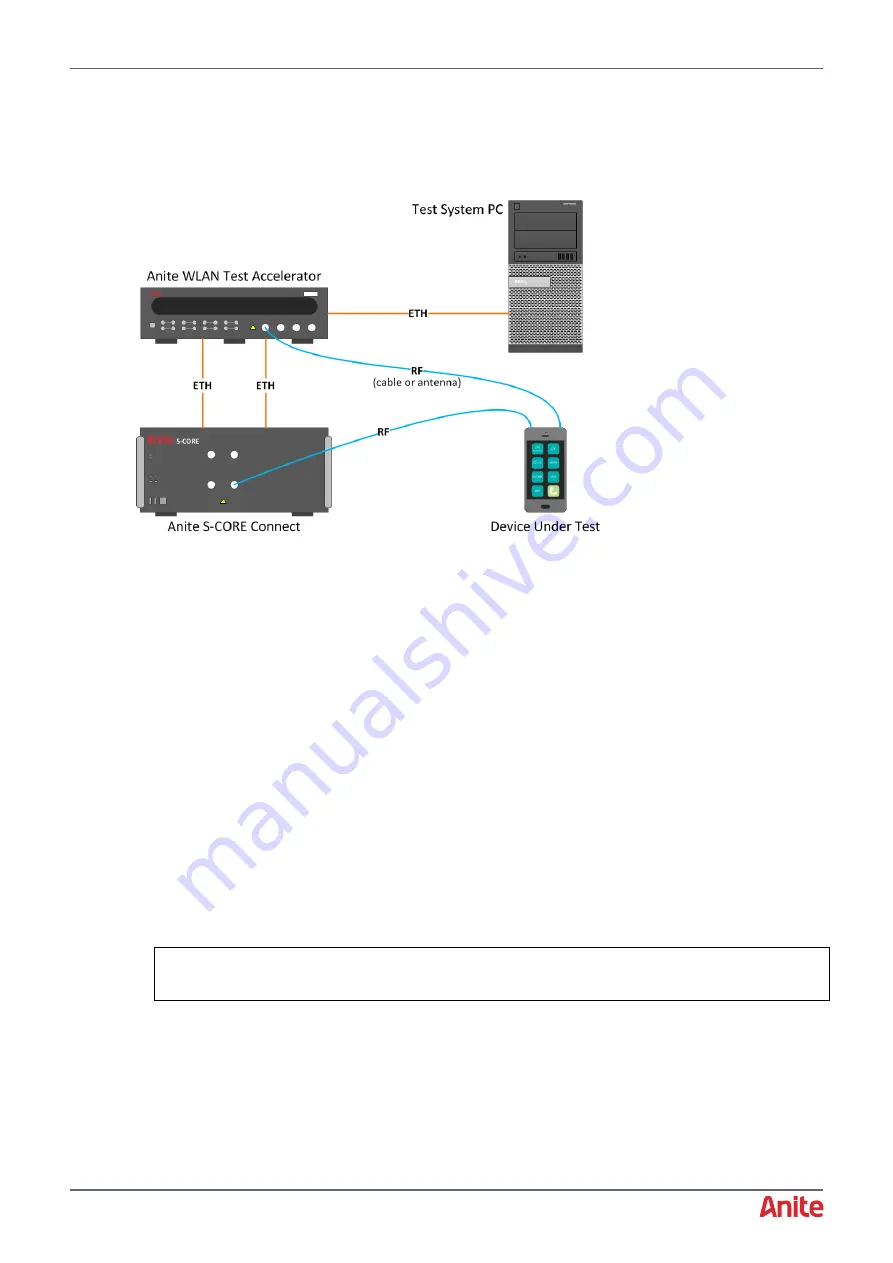
Connect the cables for the S-CORE test system using an Anite WLAN Test Accelerator as follows:
1.
Use an RF cable to connect the Device Under Test (or an Antenna Coupler) to RF Port 1A
(section 2.1 [12]) on the front of the S-CORE Connect unit.
2.
Optionally, connect a VGA Cable to the back of the S-CORE unit (section 2.1 [26]) and into a
monitor to display the S-CORE Monitor GUI, which is useful for troubleshooting. For more
information, see section A1.
3.
Connect one end of two LAN cables to the LAN Port 1 (section 2.1 [17]) and LAN Port 2 (section
2.1 [24]) connections on the back of the S-CORE
unit, and connect the other ends of the cables
to Ethernet ports on the back of the Anite WLAN Test Accelerator (section 2.3).
Note:
It is important to connect both LAN cables before using the system.
4.
Connect a LAN cable from the Ethernet port [4] on the back of the WLAN Test Accelerator to the
network card in the back of the Test System PC.
5.
Connect an RF cable with a Wi-Fi antenna on one end to the Ant 1 N-Type connector on the front
of the Anite WLAN Test Accelerator unit. The antenna on one end should be positioned close to
the UE or the coupler.
6.
Connect the S-CORE to mains using a three-prong AC power cord and into a grounded power
socket. The power input connector (type IEC 322) is located on the back of the unit (section 2.2
[30]).
Note:
Once the power input connector is switched on, you must not remove the power cable or
switch the power input connector to the off position when turning off the unit. Always use the
power button on the front of the S-CORE Connect unit.
7.
Press the power button (section 2.1 [8]) on the front panel of the S-CORE to switch it on and the
Power LED Indicator will start blinking green. This means that the system is booting up.
When the system is up, the Power LED Indicator is green and the Status LED (section 2.1 [2])
will be green.


