background image

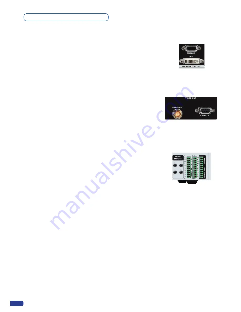
MAIN OUTPUT:

ANALOG:  1x analog output for the main display device on female  HD15 

connector.

DIGITAL/ANALOG: 1x main output on female DVI-I connector 

(simultaneous analog and digital).

VIDEO OUTPUT:

Video Output card provides SD or HDTV formats in various signals and 

connectors from Composite Video to HD SDI. This output can be used to 

record your show by outputting the same content as the Main output in Mixer 

Mode, or a choice between output #1 or #2 in Matrix Mode (see also 

OPS300


Modes, p.4).

AUDIO SWITCHER:

Audio Stereo Switcher card features 12 inputs and 2 outputs. An additional 

auxiliary input can be mixed with any other input. Master Volume and 

individual input level can be adjusted. Each input and output offers balanced 

or unbalanced connections. It should be noted that the management of the 

audio output follows the selection of video layers. Two modes are available: 

Top Follow or Breakaway. In Top Follow Mode, the audio follows the topmost 

video layer (after having pressed 

[TAKE]

). In Breakaway Mode, it is the 

selected audio layer input that is permanently diffused.

Main Outputs

24

Summary of Contents for ops300

Page 1: ...version 4 00 USER MANUAL Ops300...

Page 2: ......

Page 3: ...atrix Mode 2 1 SAFETY INSTRUCTION 2 2 UNPACKING AND INSPECTION 2 3 RACKMOUNT INFORMATION 2 4 CABLE ADAPTOR INFORMATION 2 5 HARDWARE SPECIFICATIONS 6 11 11 11 12 Input specifications Output specificati...

Page 4: ...t selection settings Source output selection Output selection settings Working with Layers Working with presets Working with audio Working with preset layouts Audio configuration Working with Cut Fade...

Page 5: ...ransitions effects Working with Audio Audio configuration OPTIONAL REMOTE CONTROL SYSTEMS 70 70 71 EXAMPLES AND TIPS 7 1 ABOUT EXAMPLES 7 2 EXAMPLES 7 3 EXTERNAL PROGRAMMING 72 72 72 74 HOW TO CONTACT...

Page 6: ...hing capabilities Output 1 and 2 can be set to different resolutions and rates Switching between any of the inputs can be done with the various effects Cut Fade Slides and synchronized on both outputs...

Page 7: ...An animated logo is also available on the eighth input KEYING a Key is an electronic process whereby an image is electronically superimposed over another source or background by cutting out either a...

Page 8: ...following guidelines The equipment connected to the network must have a release system easily accessible and located outside the unit Unplug the power cord do not pull on the power cord but always on...

Page 9: ...ranch de la prise murale Appliquer les consignes suivantes Le mat riel reli demeure au r seau doit avoir un dispositif de sectionnement facilement accessible qui doit tre incorpor l ext rieur de l app...

Page 10: ...limentazione Per assicurarsi che totalemente l apparecchio non pi collegato il cavo deve essere disconesso della presa murale Seguire le instruzioni seguenti Il materiale collegato a residenza alla re...

Page 11: ...dieses Kabel aus der Netzsteckdose ausgesteckt werden Bitte beachten Sie die folgenden Hinweise Wenn Ger te dauerhaft am Netz bleiben m ssen sie ber eine leicht zug ngliche Trennvorrichtung verf gen d...

Page 12: ...be de ser desconectado de la toma de corriente Aplicar las siguientes consignas El material conectado a residencia a la red inform tica debe de tener un dispositivo de seccionamiento f cilmente accesi...

Page 13: ...ight in excess of 2 kg 4 4 Lbs is added onto the OPS300 The maximum ambient operating temperature should not exceed 40 C 104 F The rack and all mounted equipment in it must be reliably grounded accord...

Page 14: ...5 Frequency 15 625 kHz 50 Hz 625 lines 15 734 kHz 60 Hz 525 lines Levels R G B 0 7 Vp p SYNC 0 3 Vp p or TTL negative Impedance RGB 75 ohms SYNC 75 ohms or Hi Z COMPONENT Connectors Inputs 1 to 5 fema...

Page 15: ...n Up to 1600x1200 165Mhz 1920x1200px RB Max V size 1200px Max H size 2048px SD SDI Connector SDI Inputs 1 2 female BNC Formats SMPE 259M C Data rate 270 Mbps serial digital Impedance 75 ohms HD SDI Co...

Page 16: ...16 10 50Hz 60Hz 72Hz 75Hz 1600 x 1200 4 3 50Hz 60Hz 1680 x 1050 16 10 50Hz 60Hz 1920 x 1080 16 9 50Hz 60Hz 72Hz 75Hz YES 1920 x 1080 B 16 9 50Hz 60Hz YES 1920 x 1080 C 16 9 50Hz 60Hz YES 1920 x 1080 H...

Page 17: ...72Hz 75Hz 1440 x 900 16 10 50Hz 60Hz 72Hz 75Hz 1600 x 1200 4 3 50Hz 60Hz 1680 x 1050 16 10 50Hz 60Hz 1920 x 1080 16 9 50Hz 60Hz 72Hz 75Hz YES 1920 x 1080 B 16 9 50Hz 60Hz YES 1920 x 1080 C 16 9 50Hz 6...

Page 18: ...Red green and blue wires S Video Mini 4Din white and black wires Composite Grey wire Impedence 75 ohms Cable reference for spare part 10120 COMMUNICATION PORTS REMOTE RS232 Connector DB 9 female Proto...

Page 19: ...158 F Operating humidity 10 to 80 non condensing Input voltage range 100 240 VAC 50 60 Hz Typical consumption 90 W CE Compliancy test following EN 55022 2006 A1 2007 EN 55024 1998 A1 2001 A2 2003 EN 6...

Page 20: ...Composite Sync C2 Analog Green Video or Y or Composite Video C5 Analog Common Ground Return C3 Analog Blue Video or Cb Pb DDC Display Data Channel TMDS Transition Minimized differential signal RS 232...

Page 21: ...le the HDCP receiver for the input chosen It can be very useful especially when using a Mac Input Menu DVI HDCP detection The output status can provides you all information about the output in real ti...

Page 22: ...configuration and cater for all your projection needs The intuitive rear panel of the OPS300 will let you set up for the first time quickly and easily Here is an example of a typical OPS300 setup CON...

Page 23: ...ations in this chapter The extra Video Out card installed on the OPS300 can be used for recording broadcasting or previewing purposes in a wide range of formats for maximum compatibility with industry...

Page 24: ...nt with an HD15 connector For inputs 1 to 5 connect a 1 x BNC from your composite source to the HD15 input of the device For input 8 connect 1 x BNC from your composite source to the composite RCA inp...

Page 25: ...RGB S connectors are usually BNC connectors for Broadcasting equipment and SCART connector for DVD players For inputs 1 to 5 and 8 connect a HD15 to 4 x BNC cable between the HD15 connector of the de...

Page 26: ...or 2 in Matrix Mode see also OPS300 Modes p 4 AUDIO SWITCHER Audio Stereo Switcher card features 12 inputs and 2 outputs An additional auxiliary input can be mixed with any other input Master Volume a...

Page 27: ...rtant to our users concentrating on their event The OPS300 front panel is comprised of several sections each carefully labelled and self explanatory corresponding to all the machine s versatile functi...

Page 28: ...rease or decrease any modifiable value in the OPS300 menu Simply scroll to the desired menu item and press the ENTER button to confirm your choice Control section The EXIT MENU and the ENTER button in...

Page 29: ...llows to select which input 1 to 12 to display in a selected layer Select one of 12 simultaneous inputs 8 analog inputs 2 DVI D inputs 2 SDI inputs by simply pressing one of the Input buttons The BLAC...

Page 30: ...mode the OPS300 will work in Mixer or Matrix see OPS300 Modes p 4 INPUT select to configure the 12 individual input types and resolutions MAIN OUT in Mixer Mode select to set the output types and res...

Page 31: ...ettings This operation should take approximately 30 seconds OPS300 color codes Analog Way engineers have developed a handy user friendly way of identifying machine status on the front panel via the us...

Page 32: ...eful especially using a Mac Input menu DVI HDCP detection NOTE the input status is available at any time in status input menu and can give you information about format rate and HDCP If you have any tr...

Page 33: ...ttach HDCP compliant screens or projectors If it s not the case the output image could be disabled NOTE the output status can provide you all information about the output in real time This feature is...

Page 34: ...r directly by pressing the layer button The settings available depend on the layer selected Layer adjusts set up layer size and position Layer zoom set up layer zoom size and position Size Template se...

Page 35: ...Preview to the Current Preset Main TAKE 1 shot Case 1 There are enough scalers for making a transition All inputs are locked on to scalers There are no contraints for closing before the TAKE All openi...

Page 36: ...they have to be set up before in the Control Menu Prog Keys PIPs as Layers PIP configuration All the settings and shortcuts available for layers are available for PIPs Please refer to Working with Lay...

Page 37: ...In the Layer Selection section press the PIP1 button The button will start blinking On your Preview screen PIP1 will appear as a color rectangle The parameters of the layer will automatically appear o...

Page 38: ...ith the following effects Cut Fade Slide or Wipe Capturing still Frames To capture a frame display the exact content you want to save on one of your outputs at the exact resolution you can use the FRE...

Page 39: ...Layer menu settings You can change frame or delete frame on the preview screen using the same way the layers do Delete Press BACKGROUND FRAME button Press BLACK Change Press BACKGROUND FRAME button Pr...

Page 40: ...r or input zoom A logo captures the state of the defined area on the specified output at the Main output resolution and must be recalled using the same output resolution Resizing or other image manipu...

Page 41: ...he sub menu to store the logo into Press the ENTER button The OPS300 will display a progress status bar on the VFD screen Logos as Layer Logos are under the Layer rules you will have direct access to...

Page 42: ...ob Then press the ENTER button to enter the Preset sub menu Choose Preset Copy by scrolling with the corresponding knob and press the ENTER button to access the sub menu 2 In the sub menu choose Save...

Page 43: ...ings to determine level and balance of the auxiliary input NOTE the auxiliary input is combined with the currently selected input 4 In Mixer Mode select the Main Output Menu to determine main audio ou...

Page 44: ...ckground allows you to remove the black band on sources in the background live layer in order to display behind a background frame or background color Background Frame Image Live The function disables...

Page 45: ...t and keep everything in between or invert to key only things that are of a me dium intensity The black and white levels define where to begin the keying In the range 0 to 255 0 represents no luminanc...

Page 46: ...of 255 will select nearly all hues Black Level This option permits adjustment of the luminance levels of the keyed hue The Black Level is the lumi nance lower bound Colors in the selected hue range wi...

Page 47: ...ith inter laced output format The default value of this setting is 0 for standard motion correction and can be increased up to 100 for full motion correction The correct level must be adjusted accordi...

Page 48: ...t with black bars on the sides in a 16 9 signal ANAMORPHIC Adds black bars to image to create a 1 78 image from a 4 3 signal and stretches horizontally while compres sing image vertically to fit Usefu...

Page 49: ...Output The image will be scaled to fit a 4 3 aspect Ratio The Force to 4 3 setting will not affect an image in a Fullscreen aspect Out The Force to 4 3 setting will react as an Image Setting will be r...

Page 50: ...oon as it detects a change source layer position Preset Toggle enable this feature to put you last program on your preview after a TAKE UT Bar enable disable the virtual T Bar it will appear in the Ma...

Page 51: ...en the adapted rate for your screens by using the knob button and the ENTER button Output Output Format Output rate You can also in the Output 2 menu synchronise all the changes from the Output 1 to t...

Page 52: ...on Output 2 Working with Layers Same as MIXER Mode Settings Background Live Frame Output 1 Output 2 Position NO Size NO Zoom YES Transparency YES Border NO Opening effects YES Closing effects YES Smoo...

Page 53: ...d 2 seamless transitions The background Frame and the Logos are not considered as live layers and are not counted as using a scaler Working with Native Matrix Mode To activate the Native Matrix Mode M...

Page 54: ...Mode Capturing logos Memorizing logos Working with logos Same as Mixer Mode Layer transitions effects Creating Presets Same as Mixer Mode Working with Presets Same as Mixer Mode Working with Audio Sam...

Page 55: ...EW Logo2 Logo 2 Logo 8 Logo1 Logo 1 Logo 7 Pip2 SDI 2 SDI 1 Pip1 DVI 1 DVI 2 Live Input 1 Input 8 Frame Frame 1 Frame 8 MATRIX MODE OUT 1 OUT 2 Format 1920 x 1080 Format 1920 x 1080 Rate 50Hz Rate 50H...

Page 56: ...t 2 Input 5 Input 7 Audio Input 1 SD ED HD RGBS i11 Input 3 Input 6 Input 8 Audio Input 2 SD ED HD RGsB i11 Audio Input 3 SD ED HD YUV i11 Audio Input 4 Computer SOG i11 Audio Input 5 Computer HV C i1...

Page 57: ...2 H V Internal ref RGB HV Predefined color 1366x800 15 9 75 Hz o2 H V Follow x 1 Follow x 2 RGsB SOG Saturation RGB 16 235 Disabled 1440x900 16 10 1680x1050 16 10 1920x1200 16 9 1920x1080 C 2048x1080...

Page 58: ...scale V Color bar H Color bar Grid Both Outputs SMPTE Current Output Burst o3 Output 1 Centering Output 2 Output rate 23 97 Hz o2 25 Hz o2 30 Hz o2 H Pos 60 Hz o2 V Size 50 Hz o2 V Pos 24 Hz o2 29 97...

Page 59: ...gnal R11 Interlaced signal t1 only displayed for Type Luma Key or LumaKey Titling t2 only displayed for Type Chroma Key or ChromaKey Titling t3 only displayed for Type LumaKey Titling or ChromaKey Tit...

Page 60: ...Left Corner b4 To Top Left Corner b4 From Top Right Corner b4 To Top Right Corner b4 Edge Left to Right b4 Left to Right b4 Fade Fade Vertical from Center b5 Vertical to Center b5 From Bottom Right C...

Page 61: ...e lf2 Empty if slot is free for a logo lf3 Displays only list of valid Frames and Logos lf4 Displays only for animated Logo lf5 Displays according to keying type chosen Frame 7 AUDIO Aux setting Audio...

Page 62: ...A V xxxx Input 6 L3 Device port TH V xxxx Input 8 L3 Set message ON SDI 1 L3 Clear message OFF RS232 TCP Netmask l1 xxxx l2 xxxx Input 1 L3 0 xxxx Input 3 L3 Device address MF K xxxx Input 5 L3 Gatewa...

Page 63: ...TE CONTROL SOFTWARE How to use the RCS You have to install the software on a Computer and have a LAN board or RS 232 link to use the RCS After the installation launch the program and proceed to the ne...

Page 64: ...cking on the corresponding button then navigating through the different available tabs The red window of the RCS 3 represents your Main window and can also be used much like the front panel of the OPS...

Page 65: ...main screen Ethernet connection 1 Connect a crossed RJ45 cable between the OPS300 and your PC then power on your devices Use a straight RJ45 cable if connecting through a network switcher 2 Click on t...

Page 66: ...your PC the first step in properly configuring your machine is to individually select and parameter your inputs 1 Click on the Inputs tab of the RCS 2 In the Plug column of the Input page select the p...

Page 67: ...ut format and output rate 4 Click on the Outputs tab to return to the main screen The Output menu also allows you to generate test patterns The test patterns available through the Output menu let you...

Page 68: ...he Image tab to return to the main screen Working with Frames It is possible to store up to 8 frames in the OPS300 non volatile memory Frames are mainly used as backgrounds in a typical show or event...

Page 69: ...zed positionned but also keyed via color cutout selection or Luma Key Memorizing Logos 1 In the Input Selection section click on the source button 1 to 12 of the source you wish to record as a logo 2...

Page 70: ...ine effect duration by sliding the duration bar left shorter or right longer or by manually setting the value in the duration value box 4 Repeat the procedure in the Closing Effect tab to determine th...

Page 71: ...ut and 2 embedded SDI audio inputs via the SDI BNC connectors all accessible via the Audio menu of the OPS300 and which can be affected to one or both of the 2 independent symetrical asymetrical outpu...

Page 72: ...The Axion2 integrates a offline mode for setup the devices not connected A sequences mode is also available for automatic recall of presets OPTIONAL REMOTE CONTROL SYSTEMS 6 1 Axion2 Orchestra The Orc...

Page 73: ...endly Remote Control Keypad Controls different Switchers Mini Joystick for easy ele ment control Ethernet LAN RJ45 connec tor for easy connection Large VFD display offering high contrast menu NOTE for...

Page 74: ...of our machines the most pleasant experience possible the Analog Way team is constantly aiming to create easy to follow examples update information and furnish our website with useful user information...

Page 75: ...73 SOURCES EXAMPLE 2 DOUBLE SCREEN PRESENTATION USING OPS300 in Matrix Mode...

Page 76: ...ct 2 In the Control OPS300 LAN Setup menu configure the connection of the OPS300 product in UDP mode and setup the Local and Remote Addresses as well as the Local and Remote Ports in concordance with...

Page 77: ...ing on your location See map below for information on which regional maintenance center you depend on RMA Conditions 1 Prior to returning any item you must receive a Return Material Authorization RMA...

Page 78: ...log on to www analogway com Before calling your regional maintenance center please gather the following information Serial number of the unit Firmware version look in CONTROL MENU VERSIONS Model refer...

Page 79: ......

Page 80: ...he illustrations and screens described in this manual may be exaggerated or simplified for easy recognition and may be slightly different from the actual unit ANALOG WAY SAS 33 rue du Saule Trapu Parc...

Reviews: