Appendix E – Replacing an Optima Power Suppy
83
Optima Instruction Manual
7.
If applicable
– carefully
cut the tie straps on the enclosure’s wiring harness to free the power
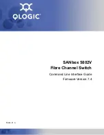
supply’s cables. Unplug the enclosure’s AC cable from the power supply’s AC connector (FIG. 59).
Note that the connector has a locking tab on the left. The other end of the AC cable remains attached
to the enclosure.
8.
Unplug the power supply’s DC cable from the Backplane (FIG. 60). Note that the connector has
double locking tabs. The other end of the DC cable remains attached to the power supply.
9.
If the power supply has a separate fan cable, unplug the power supply’s fan cable from the “FAN
PWR” connector on the Backplane (FIG. 61). If the power supply’s fan gets power from the DC
wiring harness, unplugging the DC harness in Step 8 disconnected the fan.
FIG. 59
Unplug AC connector
FIG. 60
Unplug DC connector
FIG. 61
Unplug fan cable
Power supply AC connector
AC wiring harness
DC cable
Fan cable
Summary of Contents for AutoPatch Optima AVS-OP-1616-110
Page 1: ...Instruction Manual Matrix Switchers Optima Distribution Matrix Release 05 27 2008...
Page 7: ...Contents iv Optima Instruction Manual...
Page 13: ...Notices 6 Optima Instruction Manual...
Page 47: ...Installation Setup 40 Optima Instruction Manual...
Page 79: ...Appendix D Adding or Replacing I O Boards 72 Optima Instruction Manual...
Page 99: ...Standard Video Hi Z Sync Input Output Boards 92 Optima Instruction Manual...
Page 107: ...Wideband Video 300 MHz Input Output Boards 100 Optima Instruction Manual...
Page 113: ...RGBHV HD 15 Input Output Boards 106 Optima Instruction Manual...
Page 117: ...SD SDI HD SDI Input Output Boards 110 Optima Instruction Manual...
Page 131: ...DVI Input Output Boards 124 Optima Instruction Manual...
Page 139: ...Stereo Audio Input Output Boards 132 Optima Instruction Manual...
Page 151: ...RGBHV Stereo to CatPro Input Output Boards 144 Optima Instruction Manual...
Page 163: ...XNNet Expansion Board 156 Optima Instruction Manual...