


Overview & General Specifications
11
Optima Instruction Manual
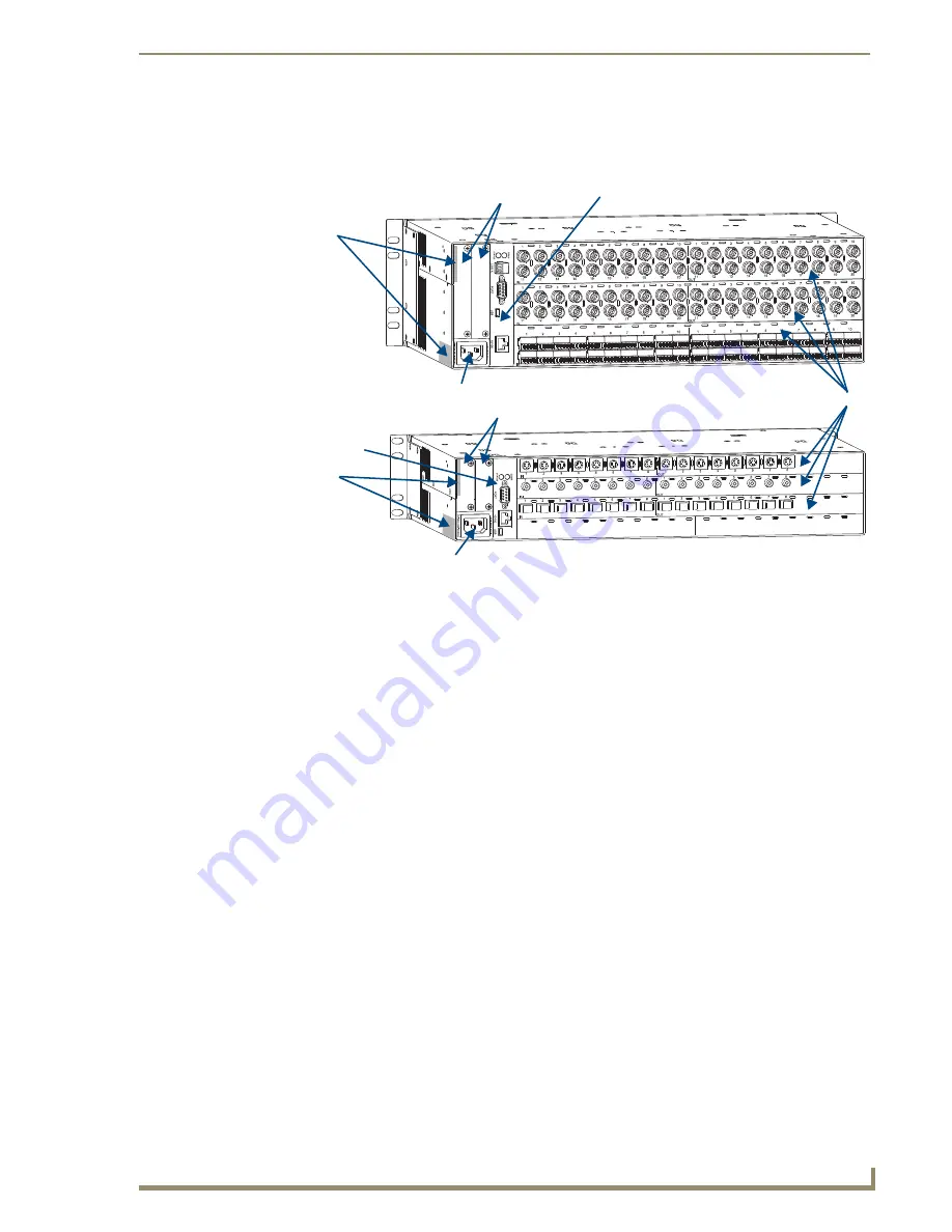
Rear View
The enclosure’s appearance, as viewed from the rear (FIG. 1), will vary depending on the configuration
and signal types.
Rear View Components
Two expansion/control slots (may contain boards for communication interfaces, etc.)
Serial number
Power receptacle and specifications
CPU/Control board
Input/output boards (number will vary depending on enclosure size, and slots may be empty
depending on the configuration)
The following sections briefly introduce the hardware on the rear of the enclosure.
FIG. 1
Rear views of Optima 3 RU and 2 RU enclosures
Input connectors
Output connectors
Input connectors
Output connectors
I/O boards
Expansion slots
CPU/Control board
Serial number
Power receptacle
Expansion slots
CPU/Control board
Serial number
Power receptacle
Summary of Contents for AutoPatch Optima AVS-OP-1616-110
Page 1: ...Instruction Manual Matrix Switchers Optima Distribution Matrix Release 05 27 2008...
Page 7: ...Contents iv Optima Instruction Manual...
Page 13: ...Notices 6 Optima Instruction Manual...
Page 47: ...Installation Setup 40 Optima Instruction Manual...
Page 79: ...Appendix D Adding or Replacing I O Boards 72 Optima Instruction Manual...
Page 99: ...Standard Video Hi Z Sync Input Output Boards 92 Optima Instruction Manual...
Page 107: ...Wideband Video 300 MHz Input Output Boards 100 Optima Instruction Manual...
Page 113: ...RGBHV HD 15 Input Output Boards 106 Optima Instruction Manual...
Page 117: ...SD SDI HD SDI Input Output Boards 110 Optima Instruction Manual...
Page 131: ...DVI Input Output Boards 124 Optima Instruction Manual...
Page 139: ...Stereo Audio Input Output Boards 132 Optima Instruction Manual...
Page 151: ...RGBHV Stereo to CatPro Input Output Boards 144 Optima Instruction Manual...
Page 163: ...XNNet Expansion Board 156 Optima Instruction Manual...


