background image

NiteHAWK Internet Jukebox 

Troubleshooting 

22022613 Rev A 


7-17 


P

ROBLEM


S

YMPTOM


P

ROBABLE 

C

AUSE


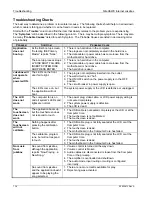
Machine is 
locked up 
during 
normal 
runtime. 

Bill acceptor is taking 
money but credits are not 
accumulating, the 
touchscreen is not 
responsive, and I/O board 
LEDs are not flashing. 

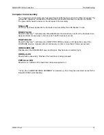
  The Computer Core is locked up.  Reboot it by 

pressing and releasing the ATX Reset Switch. 

  If the Computer Core does not boot up, perform a 

complete Power Down and Power Up. 

The bill acceptor will not 
accept a bill. 

1.  The bill acceptor is full. 
2.  The bill box was not re-installed on the bill acceptor 

correctly. 

3.  There is a jammed bill in the device. 
4.  The plugs are not inserted securely at the acceptor. 
5.  The bill acceptor is defective. 

The bill 
acceptor 
does not 
work. 

The green lights on the bill 
acceptor are not flashing. 

1.  The cable is damaged at the acceptor. 
2.  The jukebox has disabled the bill acceptor.  Put the 

jukebox into normal operating mode. 

3  The bill acceptor is defective. 

Location 
network line 
not installed 
in the 
location. 

There is no designated 
broadband line installed in 
the location. 

1.  The inside wiring installation appointment was not 

scheduled. 

2.  The inside wiring installation has not occurred. 
3.  The line was not installed in the pre-selected location. 
4.  The line (jack) was not labeled by the technician. 

When the power supply is 
connected to the router, 
nothing happens. 

1.  The AC power plug is not fully inserted in the 

receptacle on the back of the router. 

2.  Router reset circuit in power supply is defective. 
3.  The wall plug is not “hot”. 

The “Link/Act #” light (on 
the front of the router) 
does not light up when an 
Ethernet cable is plugged 
in the respective port. 

1.  The cable is loose at the Computer Core or router. 
2.  The jukebox is not powered on. 
3.  The Ethernet port is defective. 

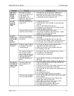
Router does 
not work. 

The WAN light does not 
light up. 

1.  The broadband connection is not plugged into the 

WAN port. 

2.  The cable modem or DSL modem is not powered on. 

The feature has never 
been available in the 
location. 

1.  There is no Ethernet cable connection between the 

router and the jukebox. 

2.  The Ethernet cable is not fully seated in the port on the 

Computer Core or in the back of the router. 

3.  The connection is loose between the installed line and 

the router. 

4.  The cable is bad. 
5.  The Internet line is down. 
6.  The hard drive trigger code was not entered. 

The “Music 
On Demand” 
feature does 
not work. 

The feature was available, 
but is no longer available. 

1.  The connection has become loose between the router 

and the jukebox. 

2.  The connection has become loose between the 

installed line (jack) and the router. 

3.  All the lights on the front of the router are ON. 
4.  The router was shut off or lost power. 
5.  The Internet service provider (ISP) is down. 
6.  The AMI Entertainment server is down. 

Summary of Contents for NiteHAWK

Page 1: ...13 Rev A Installation and Owner s Manual U S and Canada call toll free 1 877 ROC N ROL 1 877 762 6765 Outside the U S and Canada call 616 243 3633 E mail support amientertainment net www amientertainment net ...

Page 2: ......

Page 3: ...ed to AMI as components AMI extends the same warranty period as extended by the original manufacturer The above warranty applies provided that all parts of the product have been serviced properly as directed in the service manual and provided the alleged defective part upon examination by AMI shall prove to be thus defective Under no circumstances shall AMI be liable for any incidental consequenti...

Page 4: ...______________ Please complete the following This product s performance when first powered up was The overall quality of this product was The distributor support for this product was The operation manual and instructions are If there are any suggested product improvements or if problems are encountered during installation and or setup please advise in the space provided below _____________________...

Page 5: ...convenience receptacles and the point where they exit from the jukebox 10 Only use the attachments accessories specified by the manufacturer 11 Use only with the cart stand tripod bracket or table specified by the manufacturer or sold with the jukebox When a cart is used use caution when moving the cart jukebox combination to avoid injury from tip over 12 Unplug this jukebox during lightning storm...

Page 6: ...ectric shock to persons CAUTION The exclamation point within an equilateral triangle is intended to alert the user to the presence of important operating and maintenance or servicing instructions WARNING Do not expose this jukebox to rain or moisture No objects filled with liquid such as vases shall be placed on the jukebox DO NOT REMOVE ANY COVERS GUARDS OR SHIELDS NO USER SERVICEABLE PARTS ARE I...

Page 7: ... 1 6 Touchscreen 19 LCD Monitor 1 6 System Power Supply 1 6 Transformer Assembly 1 6 LED Controller 1 6 Router 1 6 Volume Control Unit 1 7 4 Channel Pre amplifier 1 7 1000 Watt Audio Digital Power Amplifier 1 7 Audio Output Transformers 1 7 Bill Acceptor 1 7 NiteHAWK Specifications 1 10 Sound System 1 10 Fuses and Circuit Breakers 1 10 Lighting 1 10 SECTION 2 INITIAL SET UP AND TESTING 2 1 Initial...

Page 8: ...bly 61182001 5 1 Features of the LED Control Assembly 61182001 Figure 5 1 5 1 Flash Rate Speed of the Perimeter LEDs 5 1 Brightness of the Perimeter and Face Graphic Panel LEDs 5 1 Music Beat Sensitivity for Perimeter LEDs 5 2 LED Flash Mode Setting for Perimeter LEDs Figure 5 2 5 2 Setting Pattern for Perimeter LEDs 5 2 Bill Acceptor Settings 5 4 Coinco Vantage Setup 5 4 MEI AE2611 Setup 5 6 SECT...

Page 9: ...Extension Speaker Worksheet Sheet 1 3 4 Table 3 2 Extension Speaker Worksheet Sheet 2 3 5 Table 3 3 Extension Speaker Worksheet Sheet 3 3 6 Table 3 4 Extension Speaker Worksheet Sheet 4 3 7 Table 3 5 Jukebox Speaker Power 3 7 Table 3 6 Jukebox Speaker Power Rock Ola Floor Models Only 3 8 ...

Page 10: ... E7 Rowe Wall Mounted Model 3 22 Figure 3 11 Low Voltage and 70V Speaker Connection to E1 E7 Rowe Wall Mounted Model 3 23 Figure 3 12 External Speaker Connection with Jukebox speakers connected to E1 E7 Rock Ola 3 24 Figure 3 13 Ten Speakers with Jukebox Speakers Connected to T3 T7 Rock Ola 3 25 Figure 3 14 Low Voltage and 70V Speakers with Jukebox Speakers Connected to T1 T7 Rock Ola 3 26 Figure ...

Page 11: ...ore Schematic Page 1 7 14 Figure 7 1 NiteHAWK Computer Core Schematic Page 2 7 15 Figure 8 1 Door Assembly External View 8 4 Figure 8 2 Door Assembly Internal View 8 6 Figure 8 3 Shell Assembly Internal View 8 8 Figure 8 4 Shell Assembly Internal View Left Hand Side 8 10 Figure 8 5 Shell Assembly Internal View Right Hand Side 8 11 Figure 8 6 Computer Core Assembly 8 12 Figure 8 7 Power Supply Asse...

Page 12: ...This page intentionally left blank ...

Page 13: ...operator and service controls All major components are modular and easy to replace if needed Computer controlled digital music A 1000 watt amplifier with dual 5 band graphic equalizer Song reject 300 album and cover art capacity Unwanted music categories can be blocked Quarter Coin Acceptance Bill acceptance of 1 5 10 and 20 Bill Box Capacity of 1000 bills Web based management Dynamic Attract mode...

Page 14: ...al or boxes until the carrier s agent has examined them Damage claims are your responsibility Do not return damaged merchandise until after your claim has been established Once your claim has been established merchandise may be returned to your Rowe distributor for repair The invoice amount for repair charges can then be collected from the carrier Door Locate the white bag in the coin return on th...

Page 15: ...e NiteHAWK is installed 2 PREFERRED METHOD At the installation location use a level to mark a line that is exactly level and 66 5 169 cm above the floor This will place the bottom of the NiteHAWK at 30 80 78 2 cm above the floor IMPORTANT This line must be level so that the mounted NiteHAWK will be level IMPORTANT If replacing a WP 100 series CD Box or an NDW 1 Duet Box use the level to mark a lin...

Page 16: ...king System Description NiteHAWK Internet Jukebox 1 4 22022613 Rev A 16 000 5 665 5 162 5 615 5 112 8 132 7 868 35 703 FLOOR 30 80 2 700 17 750 66 500 Figure 1 1 Installing the Hanger Bracket Hanger Bracket ...

Page 17: ...through the opened door to be sure the keyhole slots of the NiteHAWK Back Panel are aligned with the spools of the Hanger Bracket 2 Push the NiteHAWK against wall and lower it onto the spools 3 While the Door is still opened visually check that the NiteHAWK Back Panel is properly seated on the spool slots 4 Reinstall the Retainer Brackets and tighten the screws to lock the NiteHAWK on the Hanger B...

Page 18: ...ing the selection being played displaying pricing and credits viewing and changing setup and audit data and downloading Music On Demand selections System Power Supply The system power supply produces 9 VDC 12 VDC 24 VDC and contains a relay to switch the jukebox lights touchscreen monitor and Bill Acceptor ON or OFF It has an IEC 320 power inlet two 6A circuit breakers and two 4A fuses Transformer...

Page 19: ...up Jukebox Operation Operator Setup Screens manual for other possible configurations 4 Channel Pre amplifier This Rowelink module transforms audio signals from the Computer Core Assembly microphones and other sound processors equipment systems into signals for the Power Amplifier It contains Automatic Volume Control AVC circuits to adjust for varying recording levels and tone controls and 5 band e...

Page 20: ...ajor Components Power Transformer Computer Core Router Coin Acceptor Coin Inlet Bill Acceptor Touchscreen 19 LCD Monitor LED Controller LCD Power Adapter System Power Supply Audio Output Transformer Cabinet Fan Air Filter 4 Channel Pre amplifier 1000 Watt Digital Audio Output Transformer ...

Page 21: ...NiteHAWK Internet Jukebox Unpacking System Description 22022613 Rev A 1 9 Figure 1 4 Bottom Panel Filter and Switches Router Reset Computer Core Reset Filter ...

Page 22: ...chscreen Sound System Computer Core Type 16 bit Stereo Frequency Response 20 to 20 000 Hz Channel Separation 90 dB 1 000 Hz Output 0 7 V approx depending on the album Power Amplifier Second 1000 watt Stereo Amplifier is Optional 1000 Watt Stereo FTC Rating 2 Ohm Loads 5 THD 1000 watts RMS FTC Rating 70V Lines 5 THD 125 per channel 250 watts RMS 4 Channel Pre amplifier Channels One Stereo or Two Mo...

Page 23: ... the selected list touch the Install button at the bottom of the dialog box Testing the Network Enter the service mode by pressing and releasing the SERVICE button on the Computer Core To test the network 1 Touch the System Setup button and then touch Advanced Administration 2 On the Advanced Administration Screen touch Configure Server Then touch the Test Connection button This test confirms the ...

Page 24: ...written on the Card which was included with your new Hard Drive Touch Send Code to complete the process the message Valid Trigger Code Entered will be displayed on the screen Touch Back and then Exit Service Mode The system is now prepared for connection to the AMI Server 4 Close the jukebox and make sure that the door is locked Credit Test Insert a dollar bill into the Bill Acceptor and ensure th...

Page 25: ...ng as there is at least 1 credit under Credits in the bottom left hand corner of the screen Figure 2 3 Jukebox User Interface 1 Credit Plays Selected NOTE For Operators Pre testing the Jukebox In Their Own Facilities Any features in the application associated with the network such as the Music on Demand feature which accesses all songs in the AMI Entertainment music library will not work unless th...

Page 26: ...This page intentionally left blank ...

Page 27: ... 70 Volt Speaker Taps Left Right Ch1 A1 A2 Ch2 A1 A2 Figure 3 1 Supported Output Transformer Assemblies Extension Speaker Operation To avoid poor sound quality care must be taken when adding extension speakers The following requirements must be met Speakers connected to the Output Transformer Assembly must be wired so the power consumed by the extension speakers does not exceed the amplifier power...

Page 28: ...use of this reversal speaker connections to channel 1 must be reversed when compared to channel 2 except for 70V speaker connections See Figure 3 2 for the correct polarity hookup of extension speakers If the and terminals are not wired properly the speakers will be out of phase causing a reduction in low frequencies bass For Rowe wall model jukeboxes using 40832115 Output Transformer Assembly Cha...

Page 29: ... a directly across the amplifier E1 to E7 or T1 to T7 b connected to the 70V taps c to lower power taps on the transformer E1 through E6 or T1 through T6 2 Make the extension speaker connections 3 Perform an amplifier overload check see instructions immediately following Table 3 6 Selection Procedures Use a pencil you may want to revise your figures to fill in the Extension Speaker Worksheet on th...

Page 30: ...ity times the power consumption Place your results in the blank under Total Qty Total CH 1 CH 2 CH 1 CH 2 Two 8 ohm speakers in series 31 25 watts to each speaker ____ ____ at 62 5 watts per series ____ ____ watts Two 4 ohm speakers in series 62 5 watts to each speaker ____ ____ at 125 watts per series ____ ____ watts 8 ohm speakers ____ ____ at 125 watts each ____ ____ watts 4 ohm speakers ____ _...

Page 31: ... 49 watts each ____watts Speakers for the 64 watt taps T1 to T6 E1 to E5 ____ at 64 watts each ____watts Speakers for the 100 watt taps N A E3 to E6 ____ at 100 watts each ____watts Speakers for the 121 watt taps N A E2 to E6 ____ at 121 watts each ____watts 4 Ohm Speakers Connected to Channel 2 Transformer Taps Connections Qty Total 70251 A 40832115 Speakers for the 1 watt taps N A E1 to E2 ____ ...

Page 32: ...____ at 32 watts each ____watts Speakers for the 50 watt taps N A E3 to E6 ____ at 50 watts each ____watts Speakers for the 72 watt taps N A E1 to E6 ____ at 72 watts each ____watts Speakers for the 95 watt taps N A E3 to E7 ____ at 95 watts each ____watts 8 Ohm Speakers Connected to Channel 2 Transformer Taps Connections Qty Total 70251 A 40832115 Speakers for the 5 watt taps N A E1 to E2 ____ at...

Page 33: ...we floor model jukeboxes The jukebox wires to change are the Violet Channel 1 and the Pink Channel 2 on the Output Transformer Assembly Use Table 3 5 as a guide to select the power used by the jukebox Table 3 5 Jukebox Speaker Power Select the speaker taps for the internal jukebox speakers You may select more or less jukebox speaker power to suit your jukebox volume needs Speaker Power Jukebox Spe...

Page 34: ... extension speakers be used 3 When you have reached a satisfactory combination of speakers and speaker power consumption connect the T1 to T7 speakers and the 70V speakers to Then use the Connections column as a guide to wire the tapped T1 through T6 speakers Amplifier Overload Check Check that the amplifier is not overloaded by performing the following four steps 1 Make sure that the extension sp...

Page 35: ...This page intentionally left blank ...

Page 36: ...Sound System Setup NiteHAWK Internet Jukebox 3 10 22022613 Rev A Figure 3 2 Speaker Connections Rowe Floor Models ...

Page 37: ...NiteHAWK Internet Jukebox Sound System Setup 22022613 Rev A 3 11 ...

Page 38: ...Sound System Setup NiteHAWK Internet Jukebox 3 12 22022613 Rev A Figure 3 3 Speaker Connections Rowe Wall Mounted Model ...

Page 39: ...NiteHAWK Internet Jukebox Sound System Setup 22022613 Rev A 3 13 Extension Speakers NOTE The 70 volt phrasing is reversed inside the output transformer assembly ...

Page 40: ...Sound System Setup NiteHAWK Internet Jukebox 3 14 22022613 Rev A Figure 3 4 Speaker Connections Rock Ola ...

Page 41: ...NiteHAWK Internet Jukebox Sound System Setup 22022613 Rev A 3 15 ...

Page 42: ...Sound System Setup NiteHAWK Internet Jukebox 3 16 22022613 Rev A Figure 3 5 Audio Output Transformer Wiring Diagram 40832115 ...

Page 43: ...NiteHAWK Internet Jukebox Sound System Setup 22022613 Rev A 3 17 Figure 3 6 Audio Distribution Assembly Wiring Diagram 70251 A ...

Page 44: ...nd is by adding more speakers Using these diagrams as a guide you will readily see how many different schemes can be achieved Keep in mind that you can also disconnect the internal jukebox speakers giving you even more freedom with external speakers The key things to keep in mind are the load on each channel must be less than 500 watts and the maximum you can connect via the Output Transformers an...

Page 45: ...NiteHAWK Internet Jukebox Sound System Setup 22022613 Rev A 3 19 Figure 3 7 External Speakers with Jukebox Speakers Connected to E1 E7 Rowe Floor Model ...

Page 46: ...Sound System Setup NiteHAWK Internet Jukebox 3 20 22022613 Rev A Figure 3 8 Ten speakers with Jukebox Speakers Connected to E3 E7 Rowe Floor Model ...

Page 47: ...NiteHAWK Internet Jukebox Sound System Setup 22022613 Rev A 3 21 Figure 3 9 Low Voltage and 70V Speakers with Jukebox Speakers Connected to E1 E7 Rowe Floor Model ...

Page 48: ...Sound System Setup NiteHAWK Internet Jukebox 3 22 22022613 Rev A Figure 3 10 Ten Speaker Connected to E1 E7 Rowe Wall Mounted Model ...

Page 49: ...NiteHAWK Internet Jukebox Sound System Setup 22022613 Rev A 3 23 Figure 3 11 Low Voltage and 70V Speaker Connection to E1 E7 Rowe Wall Mounted Model ...

Page 50: ...Sound System Setup NiteHAWK Internet Jukebox 3 24 22022613 Rev A Figure 3 12 External Speaker Connection with Jukebox speakers connected to E1 E7 Rock Ola ...

Page 51: ...NiteHAWK Internet Jukebox Sound System Setup 22022613 Rev A 3 25 Figure 3 13 Ten Speakers with Jukebox Speakers Connected to T3 T7 Rock Ola ...

Page 52: ...Sound System Setup NiteHAWK Internet Jukebox 3 26 22022613 Rev A Figure 3 14 Low Voltage and 70V Speakers with Jukebox Speakers Connected to T1 T7 Rock Ola ...

Page 53: ...NiteHAWK Internet Jukebox Sound System Setup 22022613 Rev A 3 27 Figure 3 15 Volume Control Unit ...

Page 54: ...ound System Setup NiteHAWK Internet Jukebox 3 28 22022613 Rev A Figure 3 16 Volume Connections Using Existing 3 Wire or 4 Wire Cable 6 Conductor Modular Wall Jack Radio Shack Model LT 468 Catalog 279 005 ...

Page 55: ...ng Microphone Adapter that has a volume control a Rowe 50 foot microphone cable that connects between the Paging Adapter and the 4 Channel Pre amplifier and installation and operating instructions The 30995201 Paging System with Hand Held Wireless Microphone allows wireless paging and its receiver plugs into the 4 Channel Pre amplifier connectors MIC 1 or MIC 2 The wireless receiver has an output ...

Page 56: ...4 2 Make sure all MICs in the Type column are set to Paging indicated by blue buttons Figure 4 2 Paging Microphone Setup Screen The Microphone Volume During Paging is factory set to 33 for all microphones and is the recommended setting It can be set higher or lower but do not set higher than 45 If set higher than 45 the amplifier can shut down for 5 to 15 seconds if the input level is very high To...

Page 57: ... Touch VCU Setup to view the VCU Setup screen see Figure 4 3 Figure 4 3 VCU Setup Screen In the tabs VCU1 VCU4 remove the check marks in the columns corresponding with the microphones you installed by touching them This prevents location personnel from changing your settings using the VCU Touch Save to save your changes and return to Hardware Setup Touch Exit Service Mode Remove check marks ...

Page 58: ...This page intentionally left blank ...

Page 59: ...ows 1 Flashing rate speed of the perimeter LEDs 2 Brightness of the perimeter and face graphic Panel LEDs 3 Music beat sensitivity of the perimeter LEDs 4 Mode Choice of lights static in standby and beat to the music or lights flash at standby and beat to the music Perimeter lights only 5 Choice of 2 flash patterns for the perimeter lights Flash Rate Speed of the Perimeter LEDs The flash rate spee...

Page 60: ...adjust the music beat pattern Next adjust the SPEED pot clockwise until you achieve the desired effect LED Flash Mode Setting for Perimeter LEDs Figure 5 2 Program DIP Switch 1 controls the LEDs when the Jukebox is playing Beat to Music Sw OFF LEDs flash with the beat to the music Sw ON LEDs vary in brightness with the beat to the music Program DIP Switch 2 is not used Program DIP Switch 3 control...

Page 61: ...NiteHAWK Internet Jukebox LED Lighting Bill Acceptor 22022613 Rev A 5 3 Figure 5 1 LED Control Assembly Figure 5 2 Program DIP Switches ...

Page 62: ...Dollar 4 ON Always Enabled 5 OFF Pulse Mode 6 7 8 OFF For future use by Coinco In addition the Vantage has several other Configuration Settings which are made via an electronic menu system Operation and settings options are described as follows 1 To enter the Configuration More locate the Service Mode Button and Diagnostic Indicator LED as shown in Figure 5 4 Figure 5 4 Service Mode Button and Dia...

Page 63: ...ttings shown are the Rowe default settings 5 Press the Service Mode Button and release to step through the Bill Acceptance options When you have the bills enabled as desired press the Service Mode Button and hold it until the Page LED begins to blink in a 2 flash pattern 6 Set the Page 2 options as desired by pressing the Service Mode Button and releasing to step through the options When you finis...

Page 64: ...your settings have been saved 8 Refer to the Coinco Installation and Operation Guide included with your jukebox for a more detailed explanation of the various options MEI AE2611 Setup The factory DIP switch settings are 1 2 ON for 4 way acceptance 3 ON for high acceptance 4 5 OFF to accept 2 and 20 6 ON for always enable 7 OFF for one pulse per dollar 8 OFF for gaming interface Switches 6 7 and 8 ...

Page 65: ...he included manual Network Setup Jukebox Operation Operator Setup Screens and on the Web site itself Preventive Maintenance Preventive maintenance should be performed at regular intervals At every visit the exterior should be cleaned and the touchscreen should be re calibrated The interior should be cleaned every 3 4 months Exterior Part Procedure Touchscreen Clean with household glass cleaner and...

Page 66: ... Hard Drive Replacement 1 Turn off and unplug the jukebox 2 Loosen the thumbscrew securing the cover on the Computer Core and slide the cover off see Figure 6 3 3 Carefully slide the hard drive tray out of the assembly as far as cabling will allow 4 Disconnect the SATA power and data cables from the drive 5 Remove the two thumbscrews securing the hard drive to the tray 6 Secure the new hard drive ...

Page 67: ...e conditions at the site so it is best to check the filter condition at least once a month The filter is located on the bottom of the NiteHAWK as shown In Figure 6 3 Remove and clean the filter as necessary To do this remove the frame by sliding it forward as shown in Figure 6 3 Remove the filter pad from the frame Use warm water and a mild detergent to clean the filter Rinse thoroughly and allow ...

Page 68: ...This page intentionally left blank ...

Page 69: ...gh the back of connectors when mated 2 A defective module Troubleshooting procedures are directed at module replacement not repair A summary of the functions for each of the jukebox s replaceable modules is in Major Components of the NiteHAWK in Section 1 The troubleshooting topics presented in this section are The NiteHAWK indicator LEDs can help you isolate a problem A sequence of operation expl...

Page 70: ...e flashing Flashes when the 4 Channel Pre Amplifier sends an RL signal back to the Computer Core Rate is approximately twice per second Volume Control Unit Period LED on the 10s digit Should be dimly flashing at a relatively fast rate Indicates when Rowelink Master Commands are sent from the Computer Core via the Computer Core Period LED on the 1s digit Should be dimly flashing at a relatively fas...

Page 71: ...elink Master Commands are sent from the Computer Core Appears almost continuously on rate is more than 20 times per second RS485 RX LED Should be flashing Indicates when COMPUTER CORE receives an RL signal from one of the ROWELINK devices Appears almost continuously on rate is more than 20 times per second IR RECEIVER LED Flashes when the IR RECEIVER sees an IR signal May flash due to ambient ligh...

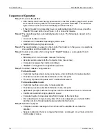
Page 72: ...ll Acceptor or Coin Acceptor receives the money Acceptor sends pulse s to the Computer Core no escrow Computer increases the credits accordingly Credit is changed on the application monitor Step 5 Customer makes a song selection For local music Customer touches album name song name and confirmation to make selection Touchscreen sends selection information to the computer The song is placed into qu...

Page 73: ...This page intentionally left blank ...

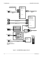
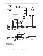
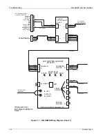
Page 74: ...PANEL DISPLAY AND TOUCH SCREEN POWER CABLE COMES WITH ROUTER 21121236 AC POWER ADAPTER TOUCH CONTROLLER CABLE COMES WITH MONITOR VGA CABLE COMES WITH MONITOR OPTIONAL 34038702 22164202 INT EXT POWER CANCEL OPTIONAL 70004 1A WIRED REMOTE 34037905 62009 A LF POWER ADAPTER COMES WITH MONITOR TO IR REMOTE Yellow ON CORE COMPUTER TO 6 BUTTON REMOTE Red ON CORE COMPUTER TO USB ON CORE COMPUTER TO COM1 O...

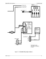
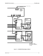
Page 75: ...H3 CH2 CH1 TO ROUTER PLUG ON POWER SUPPLY W G Y B BR Y BL 22135603 MEI BILL VALIDATOR AE2611 U7E or 22135611 COINCO VALIDATOR VL61B41US01 34037908 34022344 34039922 TO 9 PIN CONNECTOR ON POWER SUPPLY TO BILLS White ON CORE COMPUTER TO ROWELINK Green ON CORE COMPUTER 30983101 IMONEX COIN ACCEPTOR QUARTER ONLY COM N C Y GND ESCROW OOS BL NC ENABLE 5 V DATA CREDIT NC BR NC SL LED ON COIN 4 COIN 3 B C...

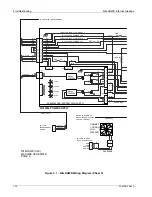
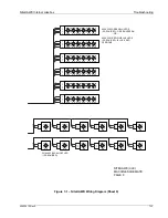
Page 76: ... G Y 120 VAC M U T E 4 34032618 W B W 120 VAC 120 VAC M U T E 1 S R Y R O 40737826 TRANSFORMER CH 1 B R G Y 50 VAC 407378231 TRANSFORMER O BL R Y R BL Optional Second Amp Kit P N 26694911 BL 50 VAC 22 VAC 34032618 50 VAC 50 VAC R CH 2 MAIN STEREO B R S R BL W B B W R BL R Y 22 VAC 22 VAC 22215009 S 20 VAC M U T E 3 O Y B Y B R 20 VAC R ROWELINK S S S 22 VAC 120 VAC BL W 34059103 O 30934222 TO ROWL...

Page 77: ...E 7 E 6 E 5 E 4 E 3 E 2 E 1 E 7 E 6 E 5 E 4 E 3 E 2 E 1 30934226 TO LED CONTROLLER S S G 61170003 1000 WATT AMPLIFIER S CH 1 CH 2 CH 2 34033402 34033402 R R B AUXILIARY OUT CH 1 61170003 1000 WATT AMPLIFIER O W 40982601 4 CHANNEL PREAMP CH 1 O B R Y 30934217 B W 70 V BR CH 3 CH 4 40832115 OUTPUT TRANSFORMERS BR R CH 3 CH 4 S O B O W CH 2 CH 4 CH 3 CH 1 CH 2 G 70 V 40832115 OUTPUT TRANSFORMERS R B ...

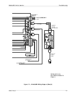
Page 78: ...EUTRAL TO BOTTOM LEAD OF PRIMARY 1 BR B R R Y G W G R W B TO TOP LEAD OF PRIMARY 2 TO BOTTOM LEAD OF PRIMARY 2 40923409 CBA SYSTEM PWR SUPPLY BL 34038808 R Y 34039922 BL S B W B Y B Y W BL W B R G Y LINE 120 22145809 POWER SUPPLY S Y S W BL B R G Y S Y S TO TOP LEAD OF PRIMARY 1 G Y O B S B W B R B RELAY CONTROL RELAY CONTROL B W B R BR W O B Y B R Y TO AMPLIFIER TRANSFORMERS SWITCHED POWER TO BIL...

Page 79: ...NS 1 2 3 1 2 3 120 V MAINS M O V MOV M O V ROUTER RESET BR W BR W Y B R Y W B W B N L W B B Y 34038808 R W R R B B R B W G Y B W B W G B W MAINS SUPPLY SELECTOR 120 VAC JUMPER ASSY 22135403 B G Y N L B W BR BL 34087701 SURGE SUPPRESSOR 21121243 21121216 POWER CORD W W G Y B 21121240 NITEHAWK CJE MACHINE SCHEMATIC PAGE 6 TO ATX POWER SUPPLY ON CORE COMPUTER TO POWER INPUT ON ROUTER ...

Page 80: ...OUT B 12 V MONEY METER SPARE IN B GND SPARE OUT A SPECIAL EVENT GND SPARE IN A 12 V LIGHTS ON OFF MUTE OUT J1 J8 AUDIO IN J2 J10 RIGHT J9 LEFT J3 J6 J5 J7 J4 BACKL R1 BRITE MUSIC R2 R4 BRITE PERIM R3 SPEED CBA LED CONTROLLER 40965701 LED CONTROLLER ASSY 61182001 PROG SW S POWER IN PERIMETER LIGHTING AUDIO IN PANEL LIGHTING SERVICE LIGHTING 12 VDC GND GND 5 VDC 5 VDC LIGHTS ON OFF 12VDC SIGNAL GND ...

Page 81: ...WH 1 2 WH WH BLUE BLUE RED WH BLUE 1 2 3 4 RED RED WH WH BLUE 1 2 3 4 RED WH 1 2 3 4 1 2 3 4 BLUE RED WH WH BLUE WH RED BLUE RED RED BLUE RED WH BLUE RED 1 2 3 4 1 2 3 4 WH WH WH BLUE BLUE RED BLUE RED 22164602 BACKLIGHT LED 12 REQUIRED NITEHAWK CJE MACHINE SCHEMATIC PAGE 8 40965301 RED WH BLUE LEDS 6 REQUIRED BLUE RED VERSIONS 40965302 GREEN WH LEDS 6 REQUIRED GREEN VERSION OR ...

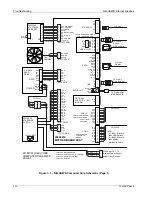
Page 82: ...202 ATX POWER SUPPLY 120 VAC INPUT NOTE 61196901 I O Board uses USB interface 61196902 I O Board uses SERIAL interface on COM2 40924212 MOTHER BOARD ASSY 40922608 MOTHER BOARD 30800429 CPU 2 6GHz DUAL PENTIUM 34039505 HEATSINK FAN ASSY 70036632 RAM 1GB POWER GROUND SENSE B R Y FAN 34039108 RX RX GND TX GND TX GND Y B B R 12 V GND GND 5 V Y B B R TX TX VCC ID_1 IN H SYNC DSR VCCb DATAa GNDb NC BLUE...

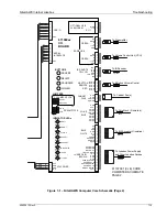
Page 83: ... IN GND LED OUT NC IR REMOTE STR A STR B RTN A RTN B RTN C STR C 6 BUTTON REMOTE CABINET NC NC GND OOS 5 V NC CREDIT ESCROW ENABLE DATA SPARE IN A SPARE IN B MUTE OUT LIGHTS ON OFF 12 V SPECIAL EVENT SPARE OUT A SPARE OUT B ROUTER POWER MONEY METER 12 V GND GND GND INHIBIT GND 12 V COIN 1 COIN 2 COIN 5 COIN 6 COIN 3 COIN 4 LED ON 611969xx I O BOARD INDICATOR LEDs JUMPERS SWITCHs OPTOs 2 CH 4 CH CO...

Page 84: ... operate when powered ON The LED s come on but the application will not boot The system power supply or the LCD is defective or unplugged The LCD does not work The computer fan is on and all system s LEDs and lights are normal 1 The power plug video cable or LCD power supply wiring is not seated completely 2 The system power supply is defective 3 The LCD is dead The touchscreen does not work The a...

Page 85: ...eled by the technician When the power supply is connected to the router nothing happens 1 The AC power plug is not fully inserted in the receptacle on the back of the router 2 Router reset circuit in power supply is defective 3 The wall plug is not hot The Link Act light on the front of the router does not light up when an Ethernet cable is plugged in the respective port 1 The cable is loose at th...

Page 86: ......
Page 87: ...ew 8 6 Figure 8 3 Shell Assembly Internal View 8 8 Figure 8 4 Shell Assembly Internal View Left Hand Side 8 10 Figure 8 5 Shell Assembly Internal View Right Hand Side 8 11 Figure 8 6 Computer Core Assembly 8 12 Figure 8 7 Power Supply Assembly 8 13 Figure 8 8 Pre amplifier 8 14 Figure 8 9 Output Transformer Assembly 8 15 Figure 8 10 Hanger Bracket Assembly 8 16 ...

Page 88: ...Number This column lists the part number to use when ordering replacement parts or making inquiries Description This column gives a word description of each part or assembly Each item is indented to show its relationship to the next higher assembly Qty This column contains the part quantity used in the assembly When a figure describes more than one model of an assembly the Qty column is divided to...

Page 89: ...This page intentionally left blank ...

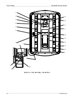
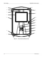
Page 90: ...Parts Catalog NiteHAWK Internet Jukebox 8 4 22022613 Rev A Figure 8 1 Door Assembly External View 10 13 5 1 14 2 4 3 7 6 15 12 8 9 6 1 11 ...

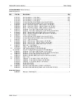
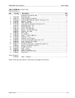
Page 91: ... 61180504 Corner Cap Gold Paint Pattern Used on 61181202 03 1 7 40964201 Cover Light Horizontal 2 8 61180201 Bezel Front Lower Blue Used on 61181201 1 61180202 Bezel Front Lower Green Used on 61181202 1 61180203 Bezel Front Lower Black Used on 61181203 1 9 34084701 Block out Card Reader 1 34085801 Label Card Reader Blockout 1 10 22135609 MEI Bill Acceptor with 1000 Bill Stacker 1 or 22135611 Coinc...

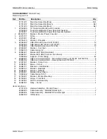
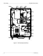
Page 92: ...Parts Catalog NiteHAWK Internet Jukebox 8 6 22022613 Rev A Figure 8 2 Door Assembly Internal View 11 6 3 3 15 16 7 19 18 17 13 14 5 1 9 8 10 2 4 12 5 20 ...

Page 93: ...3 12 6 22300901 Bracket Coin Inlet 1 7 70093103 Cable Clamp 1 4 1 8 40964401 Bracket LED CBA Horizontal 2 40964501 Bracket LED CBA Vertical Not shown 2 70500002 Support PCB Locking 42 9 40965301 CBA 6 w Controller NH1 Blue Red Used on 61181201 61180103 6 40965302 CBA 6 w Controller NH1 Green Used on 61181202 6 10 22301001 Bracket Corner Cap 4 11 34084601 Brace Corner 4 12 34084701 Blockout Card Re...

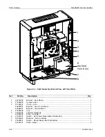
Page 94: ...Parts Catalog NiteHAWK Internet Jukebox 8 8 22022613 Rev A Figure 8 3 Shell Assembly Internal View 7 17 4 5 6 2 3 1 8 11 9 10 14 12 13 16 15 ...

Page 95: ... 40965901 Bracket Fan Filter Mounting 1 40968701 Housing Fan Filter 1 34053001 Pad Filter 1 8 34052901 Fan Assembly 1 9 21895504 Guard Finger 120MM Fan 1 10 22146801 Container Coin 1 22146901 Retainer Coin Container 1 11 40982601 4 Channel Pre amplifier See Figure 8 8 1 40982801 Cover Bottom Pre amplifier 1 12 40737831 Power Transformer 1 13 40832115 Transformer Assembly Output See Figure 8 9 1 40...

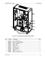
Page 96: ...8205 Coupler Latch 1 3 61182401 Chute Coin 1 40966001 Bracket Coin Chute Mount 1 40966501 Bracket Coin Deflector 1 4 21865308 Link 1 5 21947403 Lock Bar Assembly 2 21946302 Plate Lock Bar 2 6 21581801 Switch ATX Power Reset Black Pushbutton 1 7 22146901 Retainer Coin Container 1 8 25060401 Switch Router Reset Red Pushbutton 1 22142101 Plate Reset 2 8 3 4 6 behind coin box 7 1 2 5 ...

Page 97: ...lt 1 2 x 13 x 1 25 Carriage 1 92400061 Nut 1 2 13 Type 7 Not Shown 1 3 34007701 Bezel Reject Button 1 34007601 Button Reject 1 4 70163215 Cylinder Lock 1 21947501 Washer Indexing 1 21425601 Lockbolt 1 5 30781702 Cup Slug Black 1 21792901 Door Slug Cup 1 21793001 Bracket Slug Cup 1 6 40966901 Skid Rail 2 7 40966301 Bracket Cabinet Corner 4 21572601 Cable Fall Stop Not Shown 1 6 7 5 4 3 2 1 ...

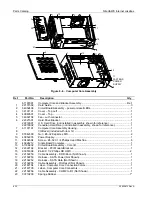
Page 98: ...using 1 8 I O Bezel included with item 12 1 9 87842300 Nut 6 32 Keps Hex MS 2 10 40952203 Power Supply 1 11 80402304 Screw 6 32 X 1 4 Phillips Head Machine 8 12 40924212 Single Board Computer 1 13 61196902 Circuit Board Assembly Core I O 1 14 22322102 Bracket PCI Modem Blockout 1 15 80351608 4 40 X 1 2 Phillips RD HMS 2 16 22132250 Cable Assembly DR Ribbon Not Shown 1 17 22132253 Harness SATA Powe...

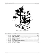
Page 99: ...902 Outlet Convenience 2 2 22118703 Power Inlet IEC 320 C 14 1 3 34038808 Harness Assembly Power Supply Only Connectors Shown 1 4 22145908 Chassis Power Supply 1 5 22141301 Standoff 8 32 x 1 5 4 6 40923409 CBA Power Supply with Router Reset 1 7 22146002 Cover Power Supply 1 8 70073606 Circuit Breaker 3 AMP 1 9 70073609 Circuit Breaker 6 AMP 2 6 4 9 7 1 2 5 1 8 3 ...

Page 100: ...14 22022613 Rev A Figure 8 8 4 Channel Pre Amplifier Ref Part No Description Qty 40982601 4 Channel Pre amplifier Assembly Ref 1 40982701 Cover Pre amplifier 1 2 61195201 CBA 4 Channel Pre amplifier 1 3 80713008 8 32 x 1 2 SEMS Hex WRHS 5 2 3 1 ...

Page 101: ...115 Output Transformer Assembly Ref 1 61133101 Chassis Audio Output 1 2 30426707 Binding Post Strip 2 3 30426706 Binding Post Strip 1 4 70233206 Bushing Snap Split 1 5 40949203 CBA Output Resistor 1 6 40633503 Transformer Output 2 Items Not Shown 34033402 Harness Assembly Output Transformer 1 21963843 Jumper Assembly 2 1 2 4 2 3 6 5 ...

Page 102: ...13 Rev A 1 2 3 4 Figure 8 10 Hanger Bracket Assembly Ref Part No Description Qty 61114003 Hanger Bracket Assembly Ref 1 87843700 10 24 Hex Keps Nut 4 2 34015401 Standoff Hanger 4 3 61114103 Hanger Weld Assembly 1 4 89973724 10 24 x 1 1 2 Carriage Bolt 4 ...

Page 103: ...ster Card 26694911 Second Amplifier Kit Add a second 1000 watt amplifier Includes a power transformer and an output transformer 34037908 100 foot cable for Volume Control Unit Replacement cable for Volume Control Unit 21958306 I R Remote Control Sending Unit Replacement spare hand held transmitter 21958305 Simplified I R Sending Unit Fewer functions that cover only the essentials of ON OFF Cancel ...

Page 104: ..._____________________________________ _______________________________________________________________________________________ _______________________________________________________________________________________ _______________________________________________________________________________________ _______________________________________________________________________________________ __________...

Reviews:

Related manuals for NiteHAWK