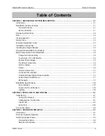
Table of Contents
NiteHAWK Internet Jukebox
vi
22022613 Rev A
Table of Figures
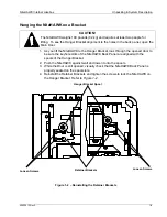
Figure 1–1 – Installing the Hanger Bracket ......................................................................................................1-4
Figure 1–2 – Reinstalling the Retainer Brackets ..............................................................................................1-5
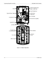
Figure 1–3 – Major Components ......................................................................................................................1-8
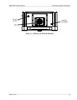
Figure 1–4 – Bottom Panel Filter and Switches ...............................................................................................1-9
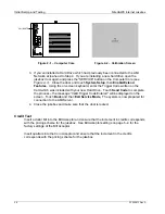
Figure 2–1 – Computer Core............................................................................................................................2-2
Figure 2–2 – Calibration Screen.......................................................................................................................2-2
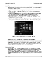
Figure 2–3 – Jukebox User Interface – “1 Credit Plays” Selected ...................................................................2-3
Figure 3–1 – Supported Output Transformer Assemblies................................................................................3-1
Figure 3–2 – Speaker Connections Rowe Floor Models................................................................................3-10
Figure 3–3 – Speaker Connections Rowe Wall-Mounted Model ...................................................................3-12
Figure 3–4 – Speaker Connections Rock-Ola................................................................................................3-14
Figure 3–5 – Audio Output Transformer Wiring Diagram (#40832115) .........................................................3-16
Figure 3–6 – Audio Distribution Assembly Wiring Diagram (70251-A) ..........................................................3-17
Figure 3–7 – External Speakers with Jukebox Speakers Connected to E1 – E7 Rowe Floor Model............3-19
Figure 3–8 – Ten speakers with Jukebox Speakers Connected to E3 – E7 Rowe Floor Model ...................3-20
Figure 3–9 – Low Voltage and 70V Speakers with Jukebox Speakers Connected to
E1 – E7 Rowe Floor Model............................................................................................................................3-21
Figure 3–10 – Ten Speaker Connected to E1 – E7 Rowe Wall-Mounted Model...........................................3-22
Figure 3–11 – Low Voltage and 70V Speaker Connection to E1 – E7 Rowe Wall-Mounted Model..............3-23
Figure 3–12 – External Speaker Connection with Jukebox speakers connected to E1 – E7 Rock-Ola ........3-24
Figure 3–13 – Ten Speakers with Jukebox Speakers Connected to T3–T7 Rock-Ola..................................3-25
Figure 3–14 – Low Voltage and 70V Speakers with Jukebox Speakers Connected to T1-T7 Rock-Ola ......3-26
Figure 3–15– Volume Control Unit .................................................................................................................3-27
Figure 3–16 – Volume Connections Using Existing 3-Wire or 4-Wire Cable 6 Conductor
Modular Wall Jack Radio Shack Model LT-468 Catalog #279-005................................................................3-28
Figure 4–1 – Microphone Connections.............................................................................................................4-1
Figure 4–2 – Paging Microphone Setup Screen ..............................................................................................4-2
Figure 4–3 – VCU Setup Screen ......................................................................................................................4-3
Figure 5–1 – LED Control Assembly ................................................................................................................5-3
Figure 5–2 – Program DIP Switches ................................................................................................................5-3
Figure 5–3 – Coinco Vantage DIP Switches ....................................................................................................5-4
Figure 5–4 – Service Mode Button and Diagnostic Indicator LED ...................................................................5-4
Figure 5–5 – Removing the Lower Housing .....................................................................................................5-5
Figure 5–6 – Configuration Settings .................................................................................................................5-5
Figure 5–7 – MEI Bill Acceptor .........................................................................................................................5-6
Figure 6–1 – Calibrate Button...........................................................................................................................6-2
Figure 6–2 – Calibration Screen.......................................................................................................................6-2
Figure 6–3 – Computer Core............................................................................................................................6-2
Figure 6–4 – Filter Removal .............................................................................................................................6-3
Figure 7–1 – NiteHAWK Wiring Diagram (Sheet 1) .........................................................................................7-6
Figure 7–1 – NiteHAWK Wiring Diagram (Sheet 2) .........................................................................................7-7
Figure 7–1 – NiteHAWK Wiring Diagram (Sheet 3) .........................................................................................7-8
Summary of Contents for NiteHAWK
Page 2: ......
Page 12: ...This page intentionally left blank ...
Page 26: ...This page intentionally left blank ...
Page 35: ...This page intentionally left blank ...
Page 37: ...NiteHAWK Internet Jukebox Sound System Setup 22022613 Rev A 3 11 ...
Page 41: ...NiteHAWK Internet Jukebox Sound System Setup 22022613 Rev A 3 15 ...
Page 58: ...This page intentionally left blank ...
Page 68: ...This page intentionally left blank ...
Page 73: ...This page intentionally left blank ...
Page 86: ......


