


NiteHAWK Internet Jukebox
Table of Contents
22022613 Rev A
vii
Figure 7–1 – NiteHAWK Wiring Diagram (Sheet 4)......................................................................................... 7-9
Figure 7–1 – NiteHAWK Wiring Diagram (Sheet 5)....................................................................................... 7-10
Figure 7–1 – NiteHAWK Wiring Diagram (Sheet 6)....................................................................................... 7-11
Figure 7–1 – NiteHAWK Wiring Diagram (Sheet 7)....................................................................................... 7-12
Figure 7–1 – NiteHAWK Wiring Diagram (Sheet 8)....................................................................................... 7-13
Figure 7–1 – NiteHAWK Computer Core Schematic (Page 1) ...................................................................... 7-14
Figure 7–1 – NiteHAWK Computer Core Schematic (Page 2) ...................................................................... 7-15
Figure 8–1 – Door Assembly (External View).................................................................................................. 8-4
Figure 8–2 – Door Assembly – Internal View................................................................................................... 8-6
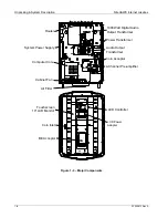
Figure 8–3 – Shell Assembly (Internal View)................................................................................................... 8-8
Figure 8–4 – Shell Assembly (Internal View, Left Hand Side) ....................................................................... 8-10
Figure 8–5 – Shell Assembly (Internal View, Right Hand Side)..................................................................... 8-11
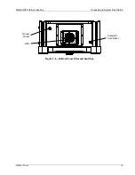
Figure 8–6 – Computer Core Assembly......................................................................................................... 8-12
Figure 8–7 – Power Supply Assembly ........................................................................................................... 8-13
Figure 8–8 – 4-Channel Pre-Amplifier ........................................................................................................... 8-14
Figure 8–9 – Output Transformer Assembly.................................................................................................. 8-15
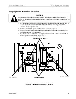
Figure 8–10 – Hanger Bracket Assembly ...................................................................................................... 8-16
Summary of Contents for NiteHAWK
Page 2: ......
Page 12: ...This page intentionally left blank ...
Page 26: ...This page intentionally left blank ...
Page 35: ...This page intentionally left blank ...
Page 37: ...NiteHAWK Internet Jukebox Sound System Setup 22022613 Rev A 3 11 ...
Page 41: ...NiteHAWK Internet Jukebox Sound System Setup 22022613 Rev A 3 15 ...
Page 58: ...This page intentionally left blank ...
Page 68: ...This page intentionally left blank ...
Page 73: ...This page intentionally left blank ...
Page 86: ......