


ReFlex Power™
DC Power Supplies
M380056-01 Rev L
6-61
appropriately hardwired prior to issuing any of the paralleling SCPI
commands.
3. Connect appropriate instrumentation for measuring the output
voltage and current, as well as a load.
4. Configure the modules into a parallel group with the following
command, where <n1> is the master module of the group.
Although the example is for two modules, it could be extended to
a greater number by listing additional parameter slot numbers,
[n]
.
SYST:GRO:DEF:PAR [n1],[n2]
5. Verify that the parallel group has been properly set up with the
following command. The response to the query is a listing of the
parallel group, the master module of the parallel group, and the
slave module of the parallel group. For example, a group of
modules with a master in slot 3 and a slave in slot 4 would return
the following parameters: 1003,3,4. The parameter,
[1000+n1]
,
is the sum of 1000 and the slot number of the master module; the
master module is the left-most module of the parallel group.
SYST:GRO:CAT:PAR?
6. Turn on the isolation and remote sense relays, turn on the output
converters, and program full-scale voltage and current with the
following commands. The parameter,
<fval>
,
is the full-scale
output voltage or current of the particular model under test. The
parameter,
[1000+n1]
, is the sum of 1000 and the slot number of
the master module; the master module is the left-most module of
the parallel group. For example, if the master module is located in
slot 1, the parameter value would be 1001.
OUTP[1000+n1]:ISOL 1
OUTP[1000+n1]:SENS 1
OUTP[1000+n1]:STAT 1
SOUR[1000+n1]:CURR <fval>
SOUR[1000+n1]:VOLT <fval>
7. Measure the output voltage and current with the external
instruments.
8. Ensure that the actual values of the output parameters are within
specifications of the programmed values.
9. Query the values of the output parameters with the following
commands:
MEAS[1000+n1]:VOLT?
MEAS[1000+n1]:CURR?
10. Ensure that the readback values of the output parameters are
within specifications of the actual values.
Summary of Contents for Elgar ReFlex Power
Page 1: ...M380056 01 Rev L www programmablepower com ReFlex Power Operation Manual...
Page 2: ......
Page 3: ......
Page 4: ......
Page 6: ...ii This page intentionally left blank...
Page 8: ...iv This page intentionally left blank...
Page 10: ...vi This page intentionally left blank...
Page 21: ...M380056 01 Rev L xvii This page intentionally left blank...
Page 22: ......
Page 85: ...ReFlex Power Controller ReFlex Power 3 22 M380056 01 Rev L This page intentionally left blank...
Page 89: ...AC Power Supplies ReFlex Power 4 4 M380056 01 Rev L Figure 4 1 ACPS Module Front Panel 875VA...
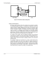
Page 120: ...ReFlex Power AC Power Supplies M380056 01 Rev L 4 35 Figure 4 11 Parallel Output Configuration...
Page 147: ...AC Power Supplies ReFlex Power 4 62 M380056 01 Rev L RST n...
Page 157: ...AC Power Supplies ReFlex Power 4 72 M380056 01 Rev L 26 Reset the unit RST n...
Page 274: ...ReFlex Power DC Power Supplies M380056 01 Rev L 6 71 18 Turn off the output RST n...
Page 275: ...DC Power Supplies ReFlex Power 6 72 M380056 01 Rev L This page intentionally left blank...
Page 279: ...Active Loads ReFlex Power 7 4 M380056 01 Rev L Figure 7 1 LPAL 375W Front Panel...
Page 280: ...ReFlex Power Active Loads M380056 01 Rev L 7 5 Figure 7 2 HPAL 750W Front Panel...
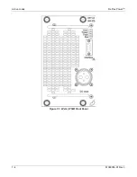
Page 281: ...Active Loads ReFlex Power 7 6 M380056 01 Rev L Figure 7 3 Typical Active Load Rear Panel...
Page 359: ...Active Loads ReFlex Power 7 84 M380056 01 Rev L This page intentionally left blank...


