


M380056-01 Rev L
ix
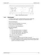
4.2.2 A
CCESSORIES
L
IST
.............................................................................................. 4-3
4.2.3 C
ONTROLS AND
I
NDICATORS
................................................................................ 4-3
4.3 SPECIFICATIONS ..................................................................... 4-5
4.3.1 P
RODUCT
M
ATRIX
................................................................................................ 4-6
4.3.2 O
UTPUT
C
HARACTERISTICS
................................................................................. 4-7
4.3.3 M
EASUREMENT
.................................................................................................... 4-9
4.3.4 S
UPERVISORY
C
HARACTERISTICS
...................................................................... 4-10
4.3.5 G
ENERAL
C
HARACTERISTICS
............................................................................. 4-10
4.3.6 I
NPUT
/O
UTPUT
C
ONNECTIONS
........................................................................... 4-11
4.3.7 C
OMMAND
S
ETS
/D
RIVERS
................................................................................. 4-12
4.3.8 M
ECHANICAL
C
HARACTERISTICS
........................................................................ 4-12
4.3.9 E
NVIRONMENTAL
C
HARACTERISTICS
................................................................. 4-13
4.3.10 R
EGULATORY
A
GENCY
C
OMPLIANCE
................................................................. 4-14
4.4 INSTALLATION ....................................................................... 4-15
4.4.1 I
NITIAL
I
NSPECTION
............................................................................................. 4-15
4.4.2 L
OCATION
C
ONSIDERATIONS
.............................................................................. 4-15
4.4.3 I
NSTALLATION
..................................................................................................... 4-16
4.4.4 I
NPUT
P
OWER
R
EQUIREMENTS
.......................................................................... 4-17
4.4.5 AC/DC
INPUT OVERCURRENT PROTECTION
....................................................... 4-20
4.4.6 AC/DC
I
NPUT
D
ISCONNECT
D
EVICE
.................................................................. 4-20
4.4.7 C
ONNECTORS
.................................................................................................... 4-21
4.4.8 W
IRE
S
ELECTION
............................................................................................... 4-25
4.5 OPERATION ............................................................................ 4-27
4.5.1 C
ONTROLS AND
I
NDICATORS
.............................................................................. 4-28
4.5.2 M
ODES OF
O
PERATION
...................................................................................... 4-29
4.5.3 L
OAD
C
ONNECTION
C
ONFIGURATIONS
............................................................... 4-31
4.5.4 D
EFAULT
O
PERATIONAL
C
ONDITIONS
................................................................ 4-38
4.5.5 I
NITIAL
F
UNCTIONAL
T
ESTS
................................................................................ 4-39
4.6 CALIBRATION ......................................................................... 4-44
4.6.1 S
COPE
............................................................................................................... 4-44
4.6.2 R
ECOMMENDED
C
ALIBRATION
E
QUIPMENT
........................................................ 4-44
4.6.3 C
ALIBRATION
S
ETUP
.......................................................................................... 4-44
4.6.4 C
AL
P
OT
C
ALIBRATION FOR
V
OLTAGE
R
ANGE
L
OW
............................................ 4-45
4.6.5 C
AL
P
OT
C
ALIBRATION
V
OLTAGE
R
ANGE
H
IGH
.................................................. 4-47
4.6.6 V
OLTAGE
ADC
O
FFSET
C
ALIBRATION FOR
V
OLTAGE
R
ANGE
L
OW
.................... 4-49
4.6.7 V
OLTAGE
ADC
O
FFSET
C
ALIBRATION FOR
V
OLTAGE
R
ANGE
H
IGH
................... 4-50
4.6.8 C
URRENT
ADC
O
FFSET
C
ALIBRATION FOR
V
OLTAGE
R
ANGE
L
OW
................... 4-51
4.6.9 C
URRENT
ADC
O
FFSET
C
ALIBRATION FOR
V
OLTAGE
R
ANGE
H
IGH
................... 4-52
4.6.10 H
IGH
S
PEED
S
UPERVISORY
C
ALIBRATION FOR
V
OLTAGE
R
ANGE
L
OW
.............. 4-53
4.6.11 H
IGH
S
PEED
S
UPERVISOR
C
ALIBRATION FOR
V
OLTAGE
R
ANGE
H
IGH
................ 4-54
4.6.12 DAC
C
ALIBRATION FOR
V
OLTAGE
R
ANGE
L
OW
................................................. 4-55
4.6.13 DAC
C
ALIBRATION FOR
V
OLTAGE
R
ANGE
H
IGH
................................................ 4-58
4.6.14 V
OLTAGE
C
ALIBRATION FOR
V
OLTAGE
R
ANGE
L
OW
.......................................... 4-61
4.6.15 V
OLTAGE
C
ALIBRATION FOR
V
OLTAGE
R
ANGE
H
IGH
.......................................... 4-64
4.6.16 LDF
C
ALIBRATION FOR
V
OLTAGE
R
ANGE
L
OW
.................................................. 4-67
4.6.17 LDF
C
ALIBRATION FOR
V
OLTAGE
R
ANGE
H
IGH
................................................. 4-69
Summary of Contents for Elgar ReFlex Power
Page 1: ...M380056 01 Rev L www programmablepower com ReFlex Power Operation Manual...
Page 2: ......
Page 3: ......
Page 4: ......
Page 6: ...ii This page intentionally left blank...
Page 8: ...iv This page intentionally left blank...
Page 10: ...vi This page intentionally left blank...
Page 21: ...M380056 01 Rev L xvii This page intentionally left blank...
Page 22: ......
Page 85: ...ReFlex Power Controller ReFlex Power 3 22 M380056 01 Rev L This page intentionally left blank...
Page 89: ...AC Power Supplies ReFlex Power 4 4 M380056 01 Rev L Figure 4 1 ACPS Module Front Panel 875VA...
Page 120: ...ReFlex Power AC Power Supplies M380056 01 Rev L 4 35 Figure 4 11 Parallel Output Configuration...
Page 147: ...AC Power Supplies ReFlex Power 4 62 M380056 01 Rev L RST n...
Page 157: ...AC Power Supplies ReFlex Power 4 72 M380056 01 Rev L 26 Reset the unit RST n...
Page 274: ...ReFlex Power DC Power Supplies M380056 01 Rev L 6 71 18 Turn off the output RST n...
Page 275: ...DC Power Supplies ReFlex Power 6 72 M380056 01 Rev L This page intentionally left blank...
Page 279: ...Active Loads ReFlex Power 7 4 M380056 01 Rev L Figure 7 1 LPAL 375W Front Panel...
Page 280: ...ReFlex Power Active Loads M380056 01 Rev L 7 5 Figure 7 2 HPAL 750W Front Panel...
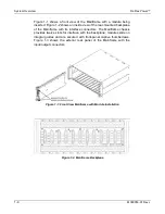
Page 281: ...Active Loads ReFlex Power 7 6 M380056 01 Rev L Figure 7 3 Typical Active Load Rear Panel...
Page 359: ...Active Loads ReFlex Power 7 84 M380056 01 Rev L This page intentionally left blank...