6 - 15
User Guide
LMG MkII
Signal Processor
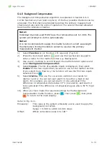
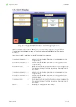
6.5.2 Alarm Mapping
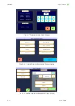
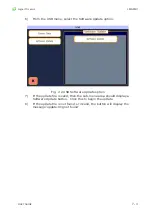
Fig. 6-17 Typical Maths Function Alarm Mapping Screen
When a Maths I/O Card is fitted, two alarm relay outputs are provided.
These can be mapped to any of the four alarms available on the Maths
function.
Use the + and – buttons to scroll though the options:
Function 1 Alarm 1 =
Alarm 1 from Maths function 1 is mapped to the
output relay
Function 1 Alarm 2 =
Alarm 2 from Maths function 1 is mapped to the
output relay
Function 1 All
=
Both alarms from maths function 1 are mapped to
the output relay. If either is active, the alarm will
be active.
Function 2 Alarm 1 =
Alarm 1 from Maths function 2 is mapped to the
output relay
Function 2 Alarm 2 =
Alarm 2 from Maths function 2 is mapped to the
output relay
Function 2 All
=
Both alarms from maths function 2 are mapped to
the output relay. If either is active, the alarm will
be active.
None
=
Nothing is mapped to the relay.
Summary of Contents for LMG MkII
Page 6: ...INTRODUCTION 1 ...
Page 10: ...INSTALLING THE PROCESSOR 2 ...
Page 14: ...User Guide 2 4 Signal Processor LMG MkII Fig 2 4 LMG MkII Electrical System Overview ...
Page 22: ...3 USING THE PROCESSOR ...
Page 44: ...TIME FUNCTION PROCESSING 4 ...
Page 50: ...SERIAL COMMUNICATIONS 5 ...
Page 62: ...Signal Processor LMG MkII Blank ...
Page 63: ...EXTERNAL I O MATHS FUNCTIONS 6 ...
Page 64: ...Signal Processor LMG MkII Screws A Fig 6 1 Location of screws on back panel Screws A ...
Page 88: ...MAINTENANCE 7 ...
Page 92: ...User Guide 7 4 Signal Processor LMG MkII Fig 7 3 USB Export Data option ...

