


User Guide
2 - 6
Signal Processor
LMG MkII
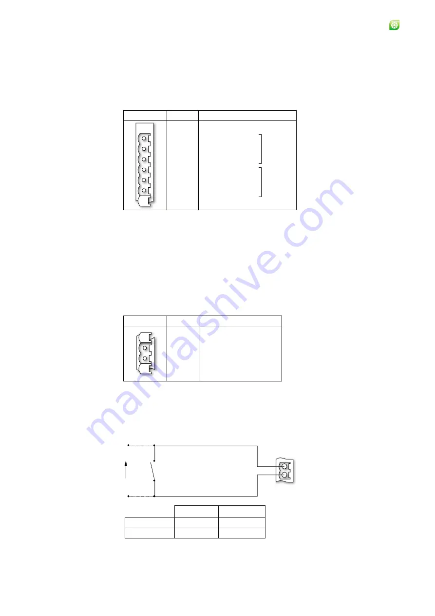
Fig. 2-7 CMD (Command) cable connection schedule
The command input can be controlled via a remote switch/relay contact, as
shown in Fig. 2-8.
2.2.1 Alarm output connection schedule
The Alarm output connection schedule is given in Fig. 2-6.
The Alarm relay contact rating is 50 V ac or dc at 0.5 A.
The alarm relays will be in their ‘Alarm’ state when power is removed.
Fig. 2-6 Alarm cable connection schedule
2.2.2 CMD (Command) input connection schedule
The CMD (Command) input connection schedule is given in Fig. 2-7.
The command signal is inactive when the voltage is >3.0 V or open circuit
(i.e. Track)
The command signal is active when the voltage is <1.5 V or short circuit (i.e.
Hold).
Fig. 2-8 CMD (Command) input control via a remote switch/relay contact
A
LA
R
M
S
Pin Nº
Function
C
NO
NC
C
NO
NC
Description
Common
Normally Open
Normally Closed
Common
Normally Open
Normally Closed
Alarm 1
Alarm 2
1
2
3
4
5
6
Pin Nº
Function
CMD+
CMD-
Description
Command input drive
Command input return
1
2
C
M
D
1
2
CMD
Remote switch /
Relay contact
Vin
Switch open
Peak Picker Track & Hold
Switch closed
Peak Pick
Reset
Track
Hold
+
-
Summary of Contents for LMG MkII
Page 6: ...INTRODUCTION 1 ...
Page 10: ...INSTALLING THE PROCESSOR 2 ...
Page 14: ...User Guide 2 4 Signal Processor LMG MkII Fig 2 4 LMG MkII Electrical System Overview ...
Page 22: ...3 USING THE PROCESSOR ...
Page 44: ...TIME FUNCTION PROCESSING 4 ...
Page 50: ...SERIAL COMMUNICATIONS 5 ...
Page 62: ...Signal Processor LMG MkII Blank ...
Page 63: ...EXTERNAL I O MATHS FUNCTIONS 6 ...
Page 64: ...Signal Processor LMG MkII Screws A Fig 6 1 Location of screws on back panel Screws A ...
Page 88: ...MAINTENANCE 7 ...
Page 92: ...User Guide 7 4 Signal Processor LMG MkII Fig 7 3 USB Export Data option ...