5 - 3
User Guide
LMG MkII
Signal Processor
5.1.1 Standard Serial Communications Card Parameters
Name Menu title text
Range
Increment
Default
Comments
Min
Max
IRT
Thermometer type
Read only
EMS Emissivity
200
1000
1
1000
e.g.
0.200 = 200
Use of correct
parameter is
determined by
irt_type value.
NGR Non-greyness
800
1250
1
1000
e.g.
1.103 =
1103
TFN
Time function
0
7
1
0
0 = None
1 = Averager
2 = Peak
picker
3 = Track &
Hold
4 = Valley
Picker
5 to 7 not used
PPM Peak picker mode
0
2
1
0
0 = Reset
1 = Hold
2 = Peak /
Valley
Sample
PPT
Peak picker
threshold
irt_tmin
irt_
tmax
1
irt_tmin = value in
degrees e.g.
1051C
Limits and units
determined by
irt_type value
PON Peak picker ON
delay
0
100
1
0
e.g. 69 =
6.9s
Seconds
POF Peak picker OFF
delay
0
100
1
100
e.g. 32 =
3.2s
Seconds
PPD
Peak picker decay
rate
0
15
1
12
0 = 0.00
1 = 0.25
2 = 0.5
3 = 1.0
4 = 2.0
5 = 4.0
6 = 8.0
7 = 16.0
8 = 32.0
9 = 64.0
10 = 128
11 = 256
12 = 512
Units are °/s
13 to 15 not used
Summary of Contents for LMG MkII
Page 6: ...INTRODUCTION 1 ...
Page 10: ...INSTALLING THE PROCESSOR 2 ...
Page 14: ...User Guide 2 4 Signal Processor LMG MkII Fig 2 4 LMG MkII Electrical System Overview ...
Page 22: ...3 USING THE PROCESSOR ...
Page 44: ...TIME FUNCTION PROCESSING 4 ...
Page 50: ...SERIAL COMMUNICATIONS 5 ...
Page 62: ...Signal Processor LMG MkII Blank ...
Page 63: ...EXTERNAL I O MATHS FUNCTIONS 6 ...
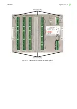
Page 64: ...Signal Processor LMG MkII Screws A Fig 6 1 Location of screws on back panel Screws A ...
Page 88: ...MAINTENANCE 7 ...
Page 92: ...User Guide 7 4 Signal Processor LMG MkII Fig 7 3 USB Export Data option ...


