RTI XP-6, Installation And Operation Manual
The RTI XP-6 boasts advanced automation features for seamless control of your home. Unlock its full potential by referring to the comprehensive Installation And Operation Manual, available for free download at manualshive.com. Get acquainted with this user-friendly manual to make the most of your RTI XP-6 experience.
Share
Download


Reviews:
No comments
Related manuals for XP-6
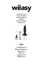
BX6
Brand: wëasy Pages: 40

FP14DCE
Brand: Cuisinart Pages: 104

Kitchen Wizz BFP400
Brand: Breville Pages: 50

Digicom Ark 3100SP
Brand: Vtron Pages: 64

R8172112K
Brand: Barco Pages: 20

17477031
Brand: PEPCOOK Pages: 44

362 HD
Brand: AUDIMAX Pages: 19

X-90
Brand: Strong International Pages: 44

00265
Brand: gourmetmaxx Pages: 32

03440
Brand: gourmetmaxx Pages: 44

78515
Brand: Unold Pages: 76

DFC1
Brand: Moulinex Pages: 19

Stack & Snap 70820
Brand: Hamilton Beach Pages: 36

CK-24V
Brand: Sammic Pages: 76

ET-ELW02
Brand: Panasonic Pages: 20

PMC-AL
Brand: Omnimount Pages: 1

TILT-PA
Brand: Omnimount Pages: 6

PJT-40
Brand: Omnimount Pages: 16


