


Chapter Three : MegaRAC® G4 Card Layout
15
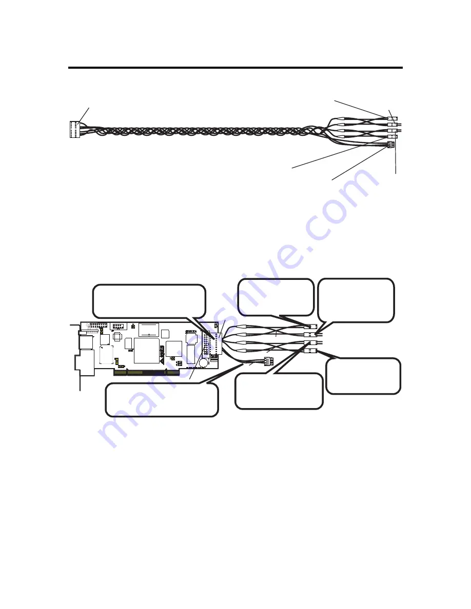
J18 MegaRAC® Feature Cable
Power On Cable
(Runs between
the MegaRAC G4
and the Power On
Switch located
on Front Panel of
the Host System)
Power On Cable
(Runs between the
MegaRAC G4 and the
Power On Header located
on the Host System’s
Motherboard)
Reset Switch Cable
(Runs between
the MegaRAC G4
and the Reset
Switch located
on Front Panel of
the Host System)
Reset Switch Cable
(Runs between
the MegaRAC G4
and the Reset
Header located
on the Host
System’s
Motherboard)
I2C Cable
(Optional, with Limitations.
Runs between the MegaRAC
G4 and the IPMB Header
located on the Host System’s
Motherboard)
MegaRAC Feature
Connector Cable
(Connects to J18)
Inspect the MegaRAC Feature Connector Cable. There are six connectors on the
MegaRAC Feature Connector Cable. One side has one connector and it plugs into the
MegaRAC card. The other end has a “Power On” pair, “Reset Switch” pair and an I2C
connector. The “Power On” pair allows you to control the power on your host system.
The “Reset Switch” pair also allows you to reset the host system. These two pair of
cables allows you to maintain you host system’s power and reset switch functionality.
Power On Cable
Reset Switch Cable
I2C Cable
MegaRAC Feature
Connector Cable
J18 MegaRAC Feature Connector
Connect the MegaRAC Feature
cable from the motherboard
to the card.
*Optional. Connect this cable to
motherboard’s IPMI/IPMB/I2C
connector.
Connect this cable
to the motherboard
Power On pins.
Connect this cable
to the motherboard
Reset pins.
Connect the cable
from the chassis
Power Switch to
these pins.
Connect the cable
from the chassis Reset
Switch to these pins.
Connect them according to the illustration above.
OEM FEATURE ONLY
:
The I2C connector attaches to your motherboard’s I2C port
(Hardware Health Monitoring port). The pin-out of the I2C port varies from
motherboard to motherboard. Also the name of the I2C port varies. It may be listed as an
IPMI or IPMB port. Your motherboard may not have this port at all. Instead, it may have
its Hardware Health Monitoring (I2C Clock and I2C) Data routed through the PCI slot.
In this case, use the jumpers at J14 and J15. If your motherboard does not have
Hardware Health Monitoring support, tie this cable so that it does not come into contact
with anything inside the chassis. The I2C connector requires that you have a Sensor
Definition Kit (SDK/SDR.DAT) file created along with a Soft Processor (SP.DAT) file.
These two files tell the MegaRAC software what it is monitoring.
Summary of Contents for MegaRAC G4
Page 1: ...MegaRAC G4 User s Guide MAN 940 01 04 07 ...
Page 28: ...MegaRAC G4 User s Guide 18 ...
Page 48: ...MegaRAC G4 User s Guide 38 ...
Page 60: ...MegaRAC G4 User s Guide 50 ...
Page 62: ...MegaRAC G4 User s Guide 52 ...


