


MegaRAC® G4 User’s Guide
6
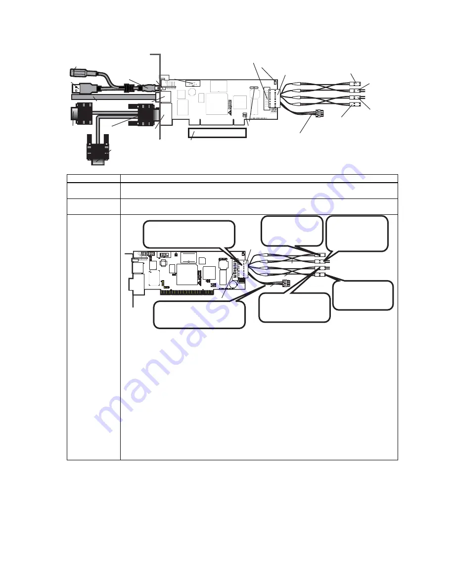
USB In
Network
VGA In
J10 RS232 Serial Port
J5 Recovery/ Configuration
J18 MegaRAC Feature Connector
J16 & J17 Must Be Shorted
J14 & J15 I2C Clock/Data PCI Bypass
Host System’s Motherboard PCI Slot
VGA Splitter Cable
RJ-45 Network Cable
Plug the AC Adapter here (optional)
To the MegaRAC G4
(USB In)
To Host System’s USB Port
Power On Cable
(Runs between
the MegaRAC G4
and the Power On
Switch located
on Front Panel of
the Host System)
Power On Cable
(Runs between the
MegaRAC G4 and the
Power On Header located
on the Host System’s
Motherboard)
Reset Switch Cable
(Runs between
the MegaRAC G4
and the Reset
Switch located
on Front Panel of
the Host System)
Reset Switch Cable
(Runs between
the MegaRAC G4
and the Reset
Header located
on the Host
System’s
Motherboard)
I2C Cable
(Optional, with Limitations. Runs between the
MegaRAC G4 and the IPMB Header located
on the Host System’s Motherboard)
To the Monitor
(15-pin Female)
To the MegaRAC G4
(15-pin Female)
To the Host System’s
VGA Port
(15-pin Male)
MegaRAC Feature
Connector Cable
(not to drawn to scale)
Connector Description
J2, J3, J4,
J11and J12
Do not use these headers if you have a MegaRAC G4 Revision E. As of Revision E, these headers
are no longer active and in the future will not be mounted on the PCB.
J10 Serial Port
You can connect an external 9 pin serial port connector to this header. This header is primarily used
to text redirect over the serial port.
J18 MegaRAC®
Feature Cable
Power On Cable
Reset Switch Cable
I2C Cable
MegaRAC Feature
Connector Cable
J18 MegaRAC Feature Connector
Connect the MegaRAC Feature
cable from the motherboard
to the card.
*Optional. Connect this cable to
motherboard’s IPMI/IPMB/I2C
connector.
Connect this cable
to the motherboard
Power On pins.
Connect this cable
to the motherboard
Reset pins.
Connect the cable
from the chassis
Power Switch to
these pins.
Connect the cable
from the chassis Reset
Switch to these pins.
Inspect the MegaRAC Feature Connector Cable. There are six connectors on the MegaRAC Feature
Connector Cable. One side has one connector and it plugs into the MegaRAC card. The other end
has a “Power On” pair, “Reset Switch” pair and an I2C connector. The “Power On” pair allows you
to control the power on your host system. The “Reset Switch” pair also allows you to reset the host
system. These two pair of cables allows you to maintain you host system’s power and reset switch
functionality. Connect them according to the illustration above.
OEM FEATURE ONLY
:
The I2C connector attaches to your motherboard’s I2C port (Hardware
Health Monitoring port). The pin-out of the I2C port varies from motherboard to motherboard. Also
the name of the I2C port varies. It may be listed as an IPMI or IPMB port. Your motherboard may
not have this port at all. Instead, it may have its Hardware Health Monitoring (I2C Clock and I2C)
Data routed through the PCI slot. In this case, use the jumpers at J14 and J15. If your motherboard
does not have Hardware Health Monitoring support, tie this cable so that it does not come into
contact with anything inside the chassis. The I2C connector requires that you have a Sensor
Definition Kit (SDK/SDR.DAT) file created along with a Soft Processor (SP.DAT) file. These two
files tell the MegaRAC software what it is monitoring.
Summary of Contents for MegaRAC G4
Page 1: ...MegaRAC G4 User s Guide MAN 940 01 04 07 ...
Page 28: ...MegaRAC G4 User s Guide 18 ...
Page 48: ...MegaRAC G4 User s Guide 38 ...
Page 60: ...MegaRAC G4 User s Guide 50 ...
Page 62: ...MegaRAC G4 User s Guide 52 ...


